Showing 282 items matching "electric motors"
-
 Wodonga & District Historical Society Inc
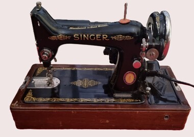
Functional object - Singer Electric Sewing Machine, The Singer Manufacturing Company, 1950
... electric motor and a light to illuminate the work area... electric motor and a light to illuminate the work area ...Singer was first established as I. M. Singer & Co. in 1851 by Isaac Merritt Singer with New York lawyer Edward C. Clark. Best known for its sewing machines, it was renamed Singer Manufacturing Company in 1865, then the Singer Company in 1963. The Singer company began to market its machines internationally in 1855 and won first prize at the Paris world's fair that year. They had offices established in both Sydney and Melbourne by the mid-1960s. The company demonstrated the first workable electric sewing machine in 1910. Singer was also a marketing innovator and a pioneer in promoting the use of instalment payment plans, making their machines more affordable for many people. According to its serial number, this machine was manufactured in 1950 and was one of the new models designed to be more portable as it only weighed about 10 KG.This sewing machine is of local, national and international significance as it represents developments in technology and the impact this had upon the work of women.The Singer 99 was a sturdy and reliable machine that was easy to use. Lighter than other machines of its time, this machine weighed only 10 Kgs. It is mounted on a wooden base with a small compartment under the balance wheel to store accessories and bobbins. It has a 'Bentwood' (polished plywood) cover which also provided some room for storage. The machine is driven by a small electric motor and a light to illuminate the work area. It is decorated with gold decals and a filigree pattern. It includes a knee control which is inserted in a hole at the front of the machine. The serial number EG045782 indicates it was manufactured in 1950.Across the top in gold script: "The Singer Manufacturing Co. / Made in Great Britain" On light cover: "SINGER" Plate with specifications also attached. On front of machine in oval badge: A CENTURY OF SEWING SERVICE/ THE SINGER MANFG. CO. 1851 - 1951singer sewing macnine, domestic appliances, women's work, technology -
 Parks Victoria - Wilsons Promontory Lightstation
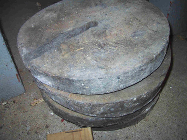
Weights
... to observe a strict roster of hours. When electric motors were... to observe a strict roster of hours. When electric motors were ...The seven weights (0008.4 and 0136.3) are circular in shape with a hole in the centre and a groove cut across the radius. They were specifically designed to fit into a weight tube, which allowed movement of the weights that were used for driving the clockwork mechanism for turning the lighthouse lens. They are most likely original to the Chance Brothers system installed in 1913, which was originally equipped with a set of ten, each weighing around thirty kilograms.The weights were moved vertically in similar fashion to the way weights move on a grandfather clock. As the weight fell, the optic clock was driven and the lens was turned. To keep the clock turning, the weight needed to be wound back up to the top of its travel. Lighthouse keepers had to constantly wind the clock to keep the light active, and at least two keepers needed to observe a strict roster of hours. When electric motors were invented, weights became obsolete and the motors were able to turn the optic for as long as there was power to drive them. Wilsons Promontory’s Chance Bros. kerosene operated light, which was turned by a clockwork mechanism, was replaced by small electric motor in 1975, reducing the number of keepers and eliminating the need for weights. Cape Schanck has a set of fourteen weights remaining in situ in the lighthouse weight tube as well as another four detached weights, two of which may be associated with the 1859 mechanism. A small number of detached cast iron weights and two associated rods remain at the Point Hicks Lightstation and one weight is displayed in the lantern room at Cape Otway.The Wilson Promontory weights have first level contributory significance for the insights they provide into the technology and operations of a late nineteenth/early twentieth century lighthouse which has since been superseded. They are well provenanced and are significant for their historical value as part of the lightstation’s Chance Brothers optical system installed in 1913.Four circular disc shaped lead weights, all with a narrow section cut out to the middle of shape. (as in slice of cake) -
 Kiewa Valley Historical Society
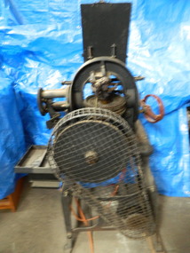
Payroll Office Machine - S.E.C.V
... Black metal table with machine on top. Electric motor... on top. Electric motor with belt drive to machine which ...This machine was used by the State Electricity Commission of Victoria on the Kiewa Hydro Electric Scheme by office workers who worked in the payroll office.The State Electricity Commission of Victoria used the latest technology available for office equipment on the Kiewa Hydro Electric Scheme. This machine was used in the payroll office.Black metal table with machine on top. Electric motor with belt drive to machine which is situated under the rear left side of the table. Safety metal mesh protects the leather belt and is at the rear of the table. The operator faces the machine which has a tray on the left and is divided longitudinally into two and holds new shiny metal plates on each side. There is a brown bakelite wheel on the left and two printing wheels inside a myriad of moving parts that enable the metal plates to be embossed with payroll information i.e. "Gang No. etc. / Names / Pay No. / Rate type. This has to be checked out each time / Date"ULQ 11 10"state electricity commission of victoria. kiewa hydro electric scheme. payroll office. office work. payroll machine. office equipment -
 Melbourne Tram Museum
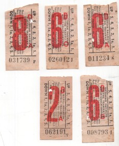
Ephemera - Ticket/s, Victorian Railways, Strip of five Victorian Railways "Electric Tramway & Motor Coach Services, c1950's
... Strip of five Victorian Railways "Electric Tramway & Motor...Strip of five Victorian Railways "Electric Tramway & Motor... Tramway Strip of five Victorian Railways "Electric Tramway & Motor ...Strip of five Victorian Railways "Electric Tramway & Motor Coach Services" Red price on off white paper. 1 - 8d - A-031739-P 2 - 6d x 3 No. O-026121-J, A-011234-K and B-0087931-J 3 - 2d A-062191-Ttrams, tramways, tickets, victorian railways, vr, st kilda brighton tramway -
 Melbourne Tram Museum
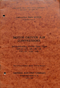
Document - Instruction, General Electric, "General Electric - Motor Driven Air-Compressors Instruction Book 84591B", Jun. 1921
... "General Electric - Motor Driven Air-Compressors... rounded corners, titled "General Electric - Motor Driven Air..., titled "General Electric - Motor Driven Air-Compressors ...Instruction - 20 pages + brown covers, centre stapled, and two punched holes on left hand side, right hand side has rounded corners, titled "General Electric - Motor Driven Air-Compressors Instruction Book 84591B", dated June 1921. Includes instructions on GE Centre Gear Type self lubricating compressors, models CP25, 27, 28, 29, 30, 127, 128 and 130. Gives details of the parts, lubrication requirements, photos, drawings including connection diagrams. Last two pages includes notes on the Induction motor-driven air compressors CPT27, 28 and 30. Has a list of company offices on the rear cover.trams, tramways, electrical engineering, electrical equipment, general electric, air compressors, brakes, instructions, maintenance -
 Bendigo Historical Society Inc.
Document - IAN DYETT COLLECTION: AUCTION CATALOGUE - GOLD DUMPS PTY LTD
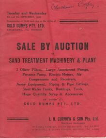
... , Electric Motors, Air Compressors and Receivers, Assay Equipment..., Large Assortment of Pumps, Pomona Pump, Electric Motors, Air ...Red covered auction catalogue for a sale held at the works of Gold Dumps Pty. Ltd., Eaglehawk on the 8th and 9th September, 1959 of Sand Treatment Machinery & Plant. Sale held at the Devonshire Sands Site and the New Moon Site. Included in the sale were 2 Oliver Filters, Large Assortment of Pumps, Pomona Pump, Electric Motors, Air Compressors and Receivers, Assay Equipment, Piping & Pipe Fittings, Steel Water Tanks, Buildings, Tools, Huge Quantity Scrap & Accessories. J. H. Curnow & Son Pty. Ltd. Were the Auctioneers. Catalogue, a Bolton Bros. Print. Auctioneers Copy written on the top of the front cover. Prices of lots have been written near the lots.business, auctioneers, j h curnow & son pty ltd, ian dyett collection - auction catalogue - gold dumps pty ltd, j h curnow & son pty ltd, devonshire sands site, new moon site, bolton bros print -
 Parks Victoria - Point Hicks Lightstation
Weights
... . When electric motors were invented, all of this became... a strict roster of hours. When electric motors were invented, all ...A small number of heavy cast iron weights and two rods remain at the Point Hicks. The weights and rods were part of the original clockwork mechanism that was fitted beneath the lens to keep the kerosene-fuelled light turning. They were attached to a cable or chains and moved vertically in similar fashion to the way weights move on grandfather clocks. As the weight fell, the optic clock was driven and the lens was turned. To keep the clock turning, the weight needed to be wound back up to the top of its travel. The cables and weights in this lighthouse were visible as they moved through the length of the tower up to the lantern room. It was usual for systems to move inside a tube extending up to the top, but in this case the tower’s cast iron spiral staircase, which is supported on cantilever cast iron brackets set into the concrete wall, spiralled around the space in which they moved. Lighthouse keepers had the arduous job of having to constantly wind the clock to keep the light active, and at least two keepers needed to observe a strict roster of hours. When electric motors were invented, all of this became redundant and the motors were able to turn the optic for as long as there was power to drive them. In December 1964, the original 1890 Chance Bros kerosene-fuelled light and clockwork mechanism were replaced by small electric motor, and the number of keepers reduced to two. The six circular weights and rods originate from the obsolete system and may have been part of a larger set. Wilsons Promontory retains seven of its original set of ten weights, all of which are detached from the tower’s weight tube. Cape Schanck has a set of fourteen weights remaining in situ as well as another four detached weights, which have inscriptions . One weight is displayed in the lantern room at Cape Otway. The Point Hicks weights have first level contributory significance for the insights they provide into the superseded technology and operations of a late nineteenth century lighthouse. They are well provenanced and are significant for their historic value as part of the lightstation’s Chance Brothers optical system installed in 1890.PHLS0005.1 Round cast iron weight with flat base used for lens clock-work mechanism attached to a bent metal rod. PHLS0005.2 Removable round cast iron weight with flat base used for lens clock-work mechanism stored above the other weight. -
 Bendigo Historical Society Inc.
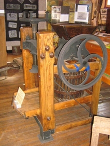
Functional object - Seal Embossing Press
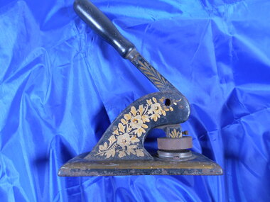
... , electric motor, etc., large stores of raw and finished material..., electric motor, etc., large stores of raw and finished material ...The Corona Paint Company Pty. Ltd. Bendigo was formed in November 1920 with £10,000 capital, in £1 shares. By July 1921, the Company had completed its factory and plant at Bendigo East, ready to begin the manufacture of paints. The Corona Paint works were opened on Saturday 28 January by the Prime Minister (Mr. Hughes) during a visit to Bendigo. Many new manufacturing industries were opened during this time after calls to address the decline of mining in the region. The factory of the CORONA PAINT COMPANY, BENDIGO, was advertised for sale in The Argus on 5 October 1923. It consisted of a “building on a railway siding, plant and machinery, including dry grinding plant, kalsomine mixer, paint mill, furnace, electric motor, etc., large stores of raw and finished material, kalsomine with range of 21 colours, oil paints, &c.”A cast iron embossing press. It's painted black with gold coulered floral decorations. The base is 18 centimetres long, nine centimetres wide and one and a half centimetres thick. A curved protrusion rises from the base that is eight centimetres by four centimetres which narrows to four centimetres by two and a half centimetres with a three-quarter centimetre wide slot. Inside the slot is a lever action with a ten centimetre by two and a half centimetre wooden handle. There is a removeable die on the end of the lever and an opposite removeable die the base. A small oval metal disc with paten no 3965 on is attached. The seal is The Corona Paint Company proprietary Limited seal embossing press, corona paint company -
 National Wool Museum
Photograph, Cooper 2-stand self contained shearing plant
... H.P. electric grinder motor circa 1948 Athol Shmith Studio... contained shearing plant powered by 1 H.P. electric grinder motor ...Photograph of Cooper shearing plant.Photograph of Coooper shearing plant.Cooper 2-stand self contained shearing plant powered by 1 H.P. electric grinder motor circa 1948 Athol Shmith Studio Illustrative Photography 125 Collins Street Melbourne C.I. Cent. 27 No. ..... Position ....... 2/F/18512shearing machinery, cooper engineering company pty ltd -
 Melbourne Tram Museum
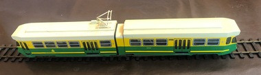
Functional object - Model tram, Preston Workshops, B1, number 2002, c1984
... sets of heavy duty electric motor, geared to two sets of four... duty electric motor, geared to two sets of four wheel bogies ...Model tram - B or B1, number 2002 made by The Met for their model tram at the Royal Show Melbourne c1985. Consists of: 1 - 2 x Fibreglass sections - one with a pantograph, painted in The Met colours with number 2002 with destination of "Special". Pantograph made from wire. 2 - small articulated section made from fibre glass and black vinyl, painted yellow and green. 3 - two sets of heavy duty electric motor, geared to two sets of four wheel bogies and one unmotorised bogie with a centre pins, washer and split pin that secured the articulated section of the tram. Each set number on side "MTA No. 7A and 9B" Made from brass, steel, plastic - purpose made. Placed with two sections of O gauge track - each 340mm long.trams, tramways, models, b class, the met, royal show -
 Ballarat Tramway Museum
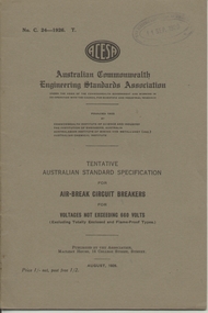
Book, Australian Commonwealth Engineering Standards Association, "Flame proof air break switches for Voltages Not Exceeding 600Volts"s", 1926-1932
... controllers and resistances for use therewith Electric Motors (DC... controllers and resistances for use therewith Electric Motors (DC ....1 - Book - 20 pages + grey covers, side stapled, issued by the Australian Commonwealth Engineering Standards Association, Tentative Australian Standard - "Air-break knife switches and laminated brush switches for voltages not exceeding 660Volts" - C23 - 1926, August 1926" .2 - Book - 24 pages + grey covers, side stapled, issued by the Australian Commonwealth Engineering Standards Association, Tentative Australian Standard - "Flame proof air break switches for Voltages Not Exceeding 600Volts", C25-1926, October 1926. .3 - Book - 24 pages + grey covers, side stapled, issued by the Australian Commonwealth Engineering Standards Association, Tentative Australian Standard - "Flame proof air break circuit breakers for Voltages Not Exceeding 600Volts", C26-1926, October 1926. .4 - Book - 24 pages + grey covers, side stapled, issued by the Australian Commonwealth Engineering Standards Association, Tentative Australian Standard - "Totally Enclosed air-break Circuit Breakers for Voltages not exceeding 660 Volts" - C27 - 1926, September 1926. .5 - Book - 24 pages + grey covers, side stapled, issued by the Australian Commonwealth Engineering Standards Association, Tentative Australian Standard - "Totally Enclosed air-break Switches for Voltages not exceeding 660 Volts" - C28 - 1926, December 1926. .6 - Book - 24 pages + grey covers, side stapled, issued by the Australian Commonwealth Engineering Standards Association, Tentative Australian Standard "Metallic Resistance Materials for Electrical Purposes" - C29-1926, November 1926. .7 - Book - 28 pages + grey covers, side stapled, issued by the Australian Commonwealth Engineering Standards Association, Tentative Australian Standard - "Face Plate controllers and resistances for use therewith Electric Motors (DC and AC Slip ring)" - C31-1926 - December 1926. .8 - Book - 28 pages + grey covers, side stapled, issued by the Australian Commonwealth Engineering Standards Association, Australian Standard "Contactor Controllers and Resistances for use therewith Electric Motors (DC and AC Slip ring)" - C32-1926 - December 1926. .9 Book - 36 pages + grey covers, side stapled, issued by the Australian Commonwealth Engineering Standards Association, Tentative Australian Standard - "Electrical Performance of Industrial Electric Motors and Generators with class A insulation" - C34-1927, October 1927 with a green label dated September 1932 advised that the tentative standard has been endorsed as a Standard with amendment. .10 - Book - 56 pages + grey covers, side stapled, issued by the Australian Commonwealth Engineering Standards Association, Tentative Australian Standard - "Electrical Performance of Large Electric Generators and Motors - Rating permitting overloads" - C35-1927, April 1927 with a green label dated September 1932 advised that the tentative standard has been endorsed as a Standard with amendment. On top right hand corner has the date stamp of the "The Electric Supply Co. of Victoria Ltd Ballarat" trams, tramways, power station, standards, materials, electrical systems -
 The Ed Muirhead Physics Museum
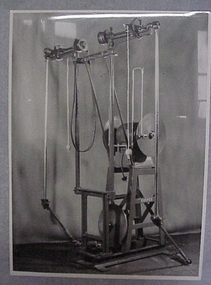
Microtome/W... (H.A. Waters)
... by a continuous action electric motor mounted on the common base. Hand... action electric motor mounted on the common base. Hand cutting ...Microtome for cutting resin embedded tissues for electron microscopy. In 1957 a modified hodge microtome redesigned and built by H.A. Waters of the Melbourne University Department of Physics was acquired. The Waters microtome is of thermal expansion type - the rod “A” is heated and by expansion pushes the resin block forward by a fraction. It is mounted on a long cast iron base. The movement of the block is eccentric drawing the specimen away from the knife after cutting, The glass knife ‘B’ is adjustable by means of a modified microscope column screws ‘C’. The microtrome is driven by a continuous action electric motor mounted on the common base. Hand cutting can also be done. The cutting was controlled by viewing through a Leitz Binocular microscope mounted on the same base. The original microscope was subjected to nine modifications by Dr S Weiner from whose PhD Thesis (1962) ‘Electron Microscopical Studies of the Liver’ this information was obtained. (text provided by Professor H Attwood) Microtome made of metal and enamelled in light blue. Components are identified by the use of stick on labels. The microtome is mounted on a long cast iron rectangular base and has an electrical cord for connection to a power point.Plaque on back: “Pathology Department, University of Melbourne Serial No. 0091. Date: 7/7/1968” -
 Harcourt Valley Heritage & Tourist Centre
Cider Press, 1880s
... to press apples. It was then belt-driven by an electric motor... by an electric motor. The press was restored (timber cleaned ...A 'BUCKEYE" grape and cider press, manufactured by P.P. Mast & Co. of Springfield, Ohio, USA and distributed by P. Rohs, Sandhurst (Bendigo). The PP Mast Company was established in 1854. Their Buckeye drills, seeders and other implements played an important role in the development of American farm machinery, being sold in every American state, Europe and Australia. This press was used by the Gaasch family of Harcourt over several generations from 1898 to crush grapes for wine and vinegar making, subsequently to crush apples and then press the pulp to make apple vinegar and cider. The crushing was accompanied by lusty singing of songs and hymns such as 'Ein Feste Burg ist unter Gott'. The press was designed to be hand-operated but was later used by Harcourt Coolstores to press apples. It was then belt-driven by an electric motor. The press was restored (timber cleaned and varnished, metal shoes on base of wooden uprights, which had rotted ) by Mr. Howard Carr, 2001-An early application of mechanics to the crushing of grapes. Hand-driven, geared drive metal crushing parts, with metal flywheel, wooden feed hopper in vertical arrangement, wooden frame, tray and vat, with metal pressing screw installed in heavy metal yoke at front. Metal crushing section carries cast-in maker's name and patent details'BUCKEYE" manufactured by P.P. Mast & Co. of Springfield, Ohio, USA distributed by P. Rohs, Sandhurst (Bendigo). -
 Bendigo Historical Society Inc.
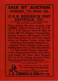
Document - IAN DYETT COLLECTION: AUCTION CATALOGUE - C.R.A. RESEARCH UNIT - EASTVILLE
... Winch with 5.5 K.W. 415 V. 3 HP Electric Motor & 100m of Cable... with 12,000 lbs. Thomas Winch with 5.5 K.W. 415 V. 3 HP Electric Motor ...Red covered auction catalogue with black printing for a sale at C.R.A. Research Unit, Eastville, Vic on 27th March 1985. For sale was Pump Setting Rig skid mounted with 12,000 lbs. Thomas Winch with 5.5 K.W. 415 V. 3 HP Electric Motor & 100m of Cable, 1981 W.B. Holden 1 Tonne Utility, Massey Ferguson 290 Tractor, 75 KVA McFarlane Generator with 6 Cyl. Diesel Motor on Tandem Trailer, Alum. Site Workshop, Steel Ships Container, 2 Uniroyal Static Storage Tanks each 50,000 gallons (U.S.), 13 Groundfos Electric S.S. Submersible Pumps, Portacom Toilet, Thousands of Metres H.D. Electrical Cable, Air Hose, Steel Flanged, Drill & P.V.C. Piping, Assorted Tools, Electrical and General Equipment. J. H. Curnow & Son Pty. Ltd. Were the auctioneers.business, auctioneers, j h curnow & son pty ltd, ian dyett collection - auction catalogue - c.r.a. research unit - eastville vic, j h curnow & son pty ltd, f c dyett, i m dyett, n f dyett, bolton bros pty ltd print -
 Parks Victoria - Point Hicks Lightstation
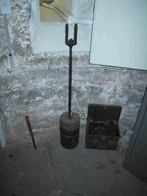
Weights
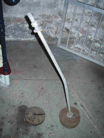
... . When electric motors were invented, all of this became... a strict roster of hours. When electric motors were invented, all ...A small number of heavy cast iron weights and two rods remain at the Point Hicks Lightstation. These weights comprise one rod with a forked top and four circular weights attached to the bottom of the shaft. The weights and rods were part of the original clockwork mechanism that was fitted beneath the lens to keep the kerosene‐fuelled light turning. They were attached to a cable or chains and moved vertically in similar fashion to the way weights move on grandfather clocks. As the weight fell, the optic clock was driven and the lens was turned. To keep the clock turning, the weight needed to be wound back up to the top of its travel. The cables and weights in this lighthouse were visible as they moved through the length of the tower up to the lantern room. It was usual for systems to move inside a tube extending up to the top, but in this case the tower’s cast iron spiral staircase, which is supported on cantilever cast iron brackets set into the concrete wall, spiralled around the space in which they moved. Lighthouse keepers had the arduous job of having to constantly wind the clock to keep the light active, and at least two keepers needed to observe a strict roster of hours. When electric motors were invented, all of this became redundant and the motors were able to turn the optic for as long as there was power to drive them. In December 1964, the original 1890 Chance Bros kerosene‐fuelled light and clockwork mechanism were replaced by small electric motor, and the number of keepers reduced to two. The six circular weights and rods originate from the obsolete system and may have been part of a larger set. Wilsons Promontory retains seven of its original set of ten weights, all of which are detached from the tower’s weight tube. Cape Schanck has a set of fourteen weights remaining in situ as well as another four detached weights, which have inscriptions. One weight is displayed in the lantern room at Cape Otway. The image shows four of the clockwork weights attached to a rod with a forked top. They were part of the original clockwork mechanism that was fitted beneath the lens to keep the kerosene‐fuelled light turning. The Aldis lamp in its case sits on the floor next to the weights. Source: Parks Victoria.The Point Hicks weights have first level contributory significance for the insights they provide into the superseded technology and operations of a late nineteenth century lighthouse. They are well provenanced and are significant for their historic value as part of the lightstation’s Chance Brothers optical system installed in 1890. Four circular metal weights are stored on a metal rod with a forked section at the top. The weights have a cut out section which allows the weights to be removed easily. -
 Melbourne Tram Museum
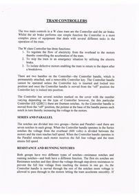
Document - Instruction, "Tram Controllers", c2000
... , its functions, electric brake and motor cut out switches.... functions, electric brake and motor cut out switches. "Tram ...Two page document, stapled in the top left hand corner, A4 photocopy - titled "Tram Controllers" describing the EE Q2RC1 controller for W class tramcars. Gives details of the controller, its functions, electric brake and motor cut out switches.trams, tramways, controllers, english electric, w class -
 Melbourne Tram Museum
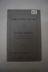
Document - Interim Report - MMTB - Upon the General Scheme for the future development of Tramways in Melbourne and Suburbs, Melbourne & Metropolitan Tramways Board (MMTB), 1922
... -electric cards, motor buses, and trolleybuses. In the conclusion...-electric cards, motor buses, and trolleybuses. In the conclusion ...An interim report by the Melbourne and Metropolitan Tramways Board (MMTB) concerning the replacement of cable tramways in Melbourne, whose capacity was predicted to be incapable of coping with future demand. In light of some opposition to electrification via overhead wires, several schemes were outlined, including a conduit system, surface contact system, battery cars, petrol cars, petrol-electric cards, motor buses, and trolleybuses. In the conclusion, the MMTB asserted that all schemes other than overhead electrification are not optimal to serving the city, and remained committed to use overhead wires.A document that clearly shows the commitment of the now-superceded public transport agency (MMTB) to electrify the Melbourne tram network.Interim Report - MMTB - Upon the General Scheme for the future development of Tramways in Melbourne and Suburbspublic transport, mmtb, tramways, electrification, electricity -
 Melbourne Tram Museum
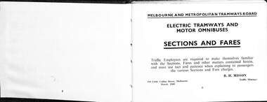
Book, Melbourne & Metropolitan Tramways Board (MMTB), "MMTB Cable and Electric Tramways and Motor Omnibuses - Sections and Fares", Jul. 1937
... "MMTB Cable and Electric Tramways and Motor Omnibuses... and end pages, "MMTB Cable and Electric Tramways and Motor... pages, "MMTB Cable and Electric Tramways and Motor Omnibuses ...Taupe coloured cloth covered book, 44 pages + covers and end pages, "MMTB Cable and Electric Tramways and Motor Omnibuses Sections and Fares" dated July 1937 and authorised by S. M Richardson. Details the various section stages and fares for each cable, electric trams and motor omnibuses, General instructions, concession fares. Has an index to routes. No photos of the various passes. Consists of one section, sewn with end papers part of the covers. 2nd copy added 5/5/2019 from donation of Barry Brooks ex Bob Prentice Collection. Images revised - jpgs retained and pdf added.trams, tramways, tickets, fares, sections, passes, cable trams, buses -
 Flagstaff Hill Maritime Museum and Village
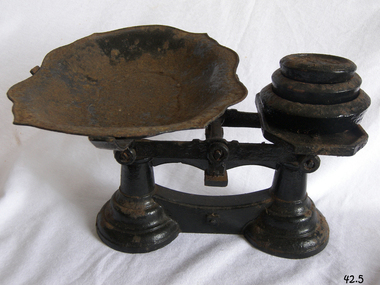
Instrument - Balance Scale, Henry Crane (Crane Foundry), 1870-1900
... for electric motors and continued to do so throughout its life... for electric motors and continued to do so throughout its life ...The Crane foundry opened some time before 1827 and was known as Atherton’s Foundry, run by James Atherton and Henry Crane. Initially it was a brass foundry, but by 1827 iron castings were also produced on the site. The main products were castings for the building industry, ironmongery and brassware. In the 1830s castings for the hand tool and lock industries were added to the product range and by 1836 Henry Crane had taken control of the business. The company became known as the Crane Foundry in 1847 with its own registered trademark. By the 1850s iron weights were produced, and a design was registered in 1872 with roundels decorating the edge. Brass weights were also produced, mainly after the regulation of 1890 that required weights of 2oz. or less to be made of brass. In the early 1900s the foundry began to produce castings for electric motors and continued to do so throughout its life. The Crane family continued to control the company until 1917 when William Cyril Parkes of lock makers Josiah Parkes & Sons Limited, Willenhall became a majority shareholder. Things were going well until the company’s liabilities spiraled out of control with the rise in electricity and gas prices along with the loss of two of the company’s largest customers. The factory went into liquidation and then closed in 2006 an end to one of Wolverhampton’s oldest companies.An item made by one of England's foundry’s based in Wolverhampton that exported items all over the world for many years. The scale gives a snapshot into the commercial life not only of England by Australian colonial life before Federation.Beam scale with three weights (4lb, 2lb, 1lb), metal tray, corrodedMarked on 2lb weight "Wolverhampton Crane Foundry" flagstaff hill, warrnambool, flagstaff hill maritime museum, shipwreck coast, flagstaff hill maritime village, great ocean road, scale, beam scale, pounds and ounces, imperial weight, grocers scale, domestic scale, henry crane, crane foundry -
 National Wool Museum
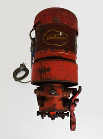
Machine - Shearing Motor, Sunbeam, 1960-69
... Electric Shearing Motor... shearing motor, for small and medium scale operations, electric... an electric shearing motor, for small and medium scale operations ...With more and more woolsheds being connected to power lines, the need for electric shearing gear markedly increased from the 1960s onwards. The greater economy made electric gear an attractive proposition to many graziers. Requiring only an electric shearing motor, for small and medium scale operations, electric shearing motors were a more economical way of shearing a wool clip. The other option for graziers was Overhead shearing gear, which also required an Engine to provide shared power to a row of shearing stations. Still working, this Sunbeam Electric Shearing Motor – Heavy Duty Model, features a slow speed motor totally enclosed for protection against dust and insects. The full bearing down tube is easily removed and stored to be out of the way when not in use (not pictured). Providing 0.5 hp, which is twice the power ever needed for shearing sheep, this buffer allows for fluctuations in voltages that can occur in rural districts. Inventor Frederick Wolseley made the world's first commercially successful power-shearing system in Australia in 1888. US company Cooper, which had been founded in 1843 as a maker of sheep dip, began selling Wolseley equipment in the USA in 1895. The Chicago Flexible Shaft Company successfully entered the power-shearing market a few years later and entered into a joint venture with Cooper. It set up a branch in Sydney and sold shearing sets, and engines to power them, into the Australian market. In 1921 the US parent company, realising it needed to make products whose sales were not as seasonal as those of shearing equipment, made its first household appliances and branded them Sunbeam. In 1933, changes in exchange rates and taxes led the company to manufacture engines and shearing equipment in Australia via subsidiary Cooper Engineering, which changed its name to Sunbeam in 1946. Although most Australians know of this company as a major manufacturer of household appliances, its rural division flourished and retained the Sunbeam name for shearing equipment even after it was taken over by New Zealand company Tru-Test in 2001. This 0.5 horsepower vertical brushed motor air-cooled engine was designed to drive a single shearing plant. From the central cylinder which features a yellow “Sunbeam” sticker, a grey 240v power lead can be found on the left-hand side. A blue capacitor is located next to this power lead. Below, two legs extend and meet to form a foot which is fastened to a wall. On the right-hand side of the engine, a specification plate is located on the central cylinder. A yellow directional arrow sticker is located on the rotating section of the engine below the specification plate (location for photography, this section is designed to rotate and hence this sticker is not fixed in this location). At the rear of the cylinder, a plastic cap with small air cut outs protects the air-cooled engine from contaminants. At the front of the engine, the location for securing the bearing down tube is located. On the right-hand side of the lock for the bearing down tube is the handle, to which a string is often attached for switching the motor on and off by a shearer bent at the waist (not pictured). Sticker. Gold writing. Front of shearing motor “Sunbeam” Plate. Inscribed. Side of shearing motor. “Sunbeam / SHEARING MOTOR / MADE IN AUSTRALIA / 0.5 H.P. / 220/240 V / 1 PHASE A.C. / 4.0 AMPS / 50 C/S. / CONT. RTG. / 1425 R.P.M. / CLASS A INSUL / NO. J244560 / TYPE: NSB5C2/49." sheep sheering, shearing equipment, sunbeam, electric shearing motor -
 Melbourne Tram Museum
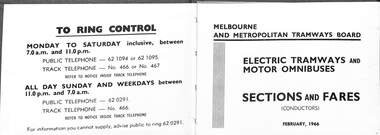
Book, Melbourne & Metropolitan Tramways Board (MMTB), "MMTB Electric Tramways and Motor Omnibuses Sections and Fares", Feb. 1966
... "MMTB Electric Tramways and Motor Omnibuses Sections and...The book titled "MMTB Electric Tramways and Motor Omnibuses... The book titled "MMTB Electric Tramways and Motor Omnibuses ...The book titled "MMTB Electric Tramways and Motor Omnibuses Sections and Fares", dated 14 Feb. 1966, the day of the introduction of decimal currency to Australia - all fares in cents. Details the various section stages and fares for each tram and bus route, General instructions, concession fares, and photos or drawings of the various special tickets, eg passes or prepaid tickets. Yields information about the Feb 1966 Fares and Sections for the MMTB at the time of the introduction of decimal currency.Green cloth covered bound book, 108 pages, plus printed end sheets used in covers. Book consists of four sections, bound with sewn cloth binding on the outside with glued white paper end covers. Dated 14 Feb. 1966, the day of the introduction of decimal currency to Australia - all fares in cents.tramways, tickets, fares, sections, decimal currency -
 Melbourne Tram Museum
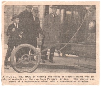
Newspaper, testing the speed of electric trams, 1920's
... showing a method of testing the speed of electric trams - using... showing a method of testing the speed of electric trams - using ...Newspaper clipping form an unknown newspaper and date showing a method of testing the speed of electric trams - using a motor-cycle wheel with a speedometer attachment. Attached to a W class tramcar at Princes Bridge. Taken during the 1920's.trams, tramways, mmtb, princes bridge, testing, specification, tramcars -
 Tatura Irrigation & Wartime Camps Museum
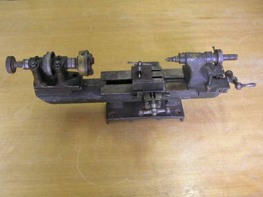
Tool - Lathe, Metal Lathe
... that was on it was a small electric sewing machine motor which was discarded about... that was on it was a small electric sewing machine motor which was discarded about ...Made at a forge outside the camp 3 perimeter by Gotthilf Kaltenbach & Manuel Kaltenbach. It is made from British Army scrap metal. Used for fine metal turning. The Witworth gauges were not used in Central Europe after 1918. The motor that was on it was a small electric sewing machine motor which was discarded about ten years ago in Germany. Sent from Germany by Elfriede & Paul Faig.Handmade metal turning lathe, 600mls long and weighing 16 kg. Made at a forge site outside the camp perimeter. All dimensions are in imperial inches, all threads are Witworth gauges. Painted in British Army colours.tatura, camp 3, lathe, metalworking, paul faig, gotthilf kaltenbach, manuel kaltenbach -
 Ballarat Tramway Museum
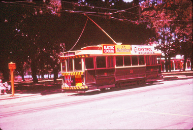
Photograph - Digital image, early 1960's
... advertisements for Electric Cooking and Castrol motor oils...., with the destination of Mt Pleasant. Has roof advertisements for Electric ...Yields information about the appearance of tram at Gardens Loop during the early 1960'sDigital images scanned from 35mm slides, possibly a copy slide obtained by John Theodore from the BTPS Sales of tram 32, at Gardens Loop, with the destination of Mt Pleasant. Has roof advertisements for Electric Cooking and Castrol motor oils.trams, tramways, wendouree parade, gardens loop, tram 32 -
 Melbourne Tram Museum
Book, Melbourne & Metropolitan Tramways Board (MMTB), "MMTB Electric Tramways and Motor Omnibuses Sections and Fares", Mar. 1960
... "MMTB Electric Tramways and Motor Omnibuses Sections and...Book titled "MMTB Electric Tramways and Motor Omnibuses... titled "MMTB Electric Tramways and Motor Omnibuses Sections ...Book titled "MMTB Electric Tramways and Motor Omnibuses Sections and Fares", dated March 1960. Details the various section stages and fares for each tram and bus route, General instructions, concession fares and photos or drawings of the various special tickets, eg passes or prepaid tickets. See item 7352 for a version of the same date but different cover sheets. Not known which one proceeded - could have been a reprint.Yields information about the March 1960 Fares and Sections for the MMTB.Black cloth covered bound book, 124 pages, plus printed end sheets used in covers. Book consists of four sections, bound with sewn cloth binding on the outside with glued white paper end covers.Multiple ink markingstrams, tramways, tickets, fares, sections, passes -
 Eltham District Historical Society Inc
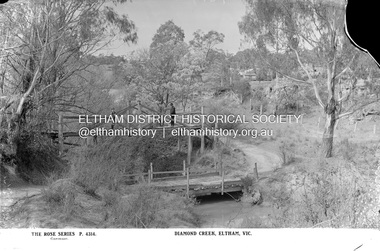
Negative - Photograph, The Rose Stereograph Company, Diamond Creek, Eltham, Vic, c.1919
... as a steam locomotive hauled carriage and in 1919 electric motor... as a steam locomotive hauled carriage and in 1919 electric motor ...Shows two bridge crossings over the Diamond Creek in Diamond Street, Eltham. The upper pedestrian crossing provided continual access for foot traffic during times of flood. The railway came to Eltham in 1901, the Eltham Railway Station is visible in the distance as well as a wooden bodied Tait (Red Rattler) First Class train carriage. The Tait train was first introduced in 1910 as a steam locomotive hauled carriage and in 1919 electric motor carriages were introduced however the line to Heidelberg was not electrified till 1921 and to Eltham in April 1923. The Railway General Store on Main Road is visible beyond the station and was built by Luther Haley in 1902. It was the first shop in the present day shopping centre. It was later known as lloyd's stopre (1917-1920) followed by a succession of six other owners until purchased by Eric Staff in 1939. This glass plate negative was used to manufacture postcards (1:1 printing) for commercial sale by the Rose Sterograph Company and its subsidiaries. George Rose founded the Rose Stereograph Company in 1880 and was joined by Herbert (Bert) Cutts in the early 20th Century. The pair formed a lifetime working partnership and strong personal friendship. Assisted by George’s two sons, Herbert George and Walter, and later by Neil Cutts, the Rose Stereograph Company continued its operations for more than 140 years. The company was initially built on stereographs, but as cinema took over and stereographs fell out of fashion, the Rose Stereograph Company developed Australia’s first commercially viable photographic postcard business. Specialising in postcards of iconic historical moments and significant landmarks, The Rose Stereograph Company became a staple of the Australian travel industry.This remarkable collection of glass plate negatives, transparencies, and postcards – arguably Australia’s most significant photography collection outside of public hands – has been passed down through the generations, surviving war, relocation, and the harsh Victorian climate. The historic Rose Stereograph collection is the culmination of George Rose’s dream of capturing and preserving precious moments in time and remains the legacy of the Rose and Cutts families. It is with great sadness that the Cutts family says goodbye to a collection that spans five generations and 140 years. The Cutts family understands that for these historically important pieces to rest with one family is to deny others the pleasure of their custodianship.Glass Plate Negative Size: 9 x 13.9 cmDiamond Creek, Eltham, Vic., The Rose Series P. 4314, Copyrighteltham, postcard, travel, rose stereograph company, glass plate negative, rose series postcard, tait train, eltham railway station, railway store, staffs general store, diamond creek, diamond street bridge, lloyd's general store, railway station, peter and elizabeth pidgeon collection -
 Eltham District Historical Society Inc
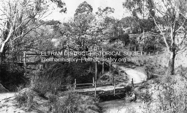
Negative - Photograph, Diamond Creek, Eltham. Old Diamond Street Bridge
... as a steam locomotive hauled carriage and in 1919 electric motor... electric motor carriages were introduced however the line ...Copy of Rose Series Postcard P. 4314. (The Rose Stereograph Company) Shows two bridge crossings over the Diamond Creek in Diamond Street, Eltham. The upper pedestrian crossing provided continual access for foot traffic during times of flood. The railway came to Eltham in 1901, the Eltham Railway Station is visible in the distance as well as a wooden bodied Tait (Red Rattler) First Class train carriage. The Tait train was first introduced in 1910 as a steam locomotive hauled carriage and in 1919 electric motor carriages were introduced however the line to Heidelberg was not electrified till 1921 and to Eltham in April 1923. The Railway General Store on Main Road is visible beyond the station and was built by Luther Haley in 1902. It was the first shop in the present day shopping centre. It was later known as lloyd's stopre (1917-1920) followed by a succession of six other owners until purchased by Eric Staff in 1939. George Rose founded the Rose Stereograph Company in 1880 and was joined by Herbert (Bert) Cutts in the early 20th Century. The pair formed a lifetime working partnership and strong personal friendship. Assisted by George’s two sons, Herbert George and Walter, and later by Neil Cutts, the Rose Stereograph Company continued its operations for more than 140 years. The company was initially built on stereographs, but as cinema took over and stereographs fell out of fashion, the Rose Stereograph Company developed Australia’s first commercially viable photographic postcard business. Specialising in postcards of iconic historical moments and significant landmarks, The Rose Stereograph Company became a staple of the Australian travel industry.This photo forms part of a collection of photographs gathered by the Shire of Eltham for their centenary project book,"Pioneers and Painters: 100 years of the Shire of Eltham" by Alan Marshall (1971). The collection of over 500 images is held in partnership between Eltham District Historical Society and Yarra Plenty Regional Library (Eltham Library) and is now formally known as 'The Shire of Eltham Pioneers Photograph Collection.' It is significant in being the first community sourced collection representing the places and people of the Shire's first one hundred years.Digital image 4 x 5 inch B&W Negdiamond creek, diamond street bridge, eltham, eltham railway station, glass plate negative, lloyd's general store, postcard, railway station, railway store, rose series postcard, rose stereograph company, shire of eltham pioneers photograph collection, staffs general store, tait train, travel -
 Puffing Billy Railway
New Record Saw Bench, circa 1930's
... largely supplanted by electric motors. The Champion..., and in turn petrol engines were largely supplanted by electric motors ...Saw Bench - New Record Saw Bench Timber framed with steel wheels, belt driven saw blade powered by a Rosbery internal combustion engine. The Rosebery Engine No C28437 R.P.M 800 H.P. 6 Manufactured By Westinghouse Rosebery Pty.Ltd. Sydney Rosebery Engine Works Ltd began as the engine and pump manufacturing division of Buzacott & Company, and in 1923 became an incorporated company. In 1935, Westinghouse gave Rosebery Engine Works the right to manufacture and sell nearly all Westinghouse products. The name of the company then changed to Westinghouse Rosebery Ltd From the late nineteenth century, petrol engines gradually supplanted steam engines for running a wide range of machines, and in turn petrol engines were largely supplanted by electric motors. The Champion was a successful small petrol engine made by the large Sydney company, Westinghouse Rosebery, based on the American-designed Fuller and Johnson engine. With hopper cooling and a fuel tank between the skids, and weighing only 240 pounds (109 kg), it was easy to mount on wheeled transport, making the Champion a self-contained mobile source of power. Engines of this type were used in rural areas for driving chaff cutters, small saw benches, pumps and orchard sprayers. These engines were also commonly used in both rural and urban areas for powering concrete mixers. Both Westinghouse Rosebery in NSW and Toowoomba Foundry in Queensland made these engines in large quantities, beginning in the 1920s when tariff protection made local manufacturing viable. The production of small petrol engines continued in Australia until the 1970s, when reduced tariff protection led to increased competition from cheaper imported engines. Historic - Industrial Timber working - belt driven saw blade powered by a Rosbery internal combustion engine. Timber framed with steel wheels, belt driven saw blade powered by a Rosbery internal combustion engine. The Rosebery Engine No c28437 R.P.M 800 H.P. 6 Manufactured By Westinghouse Rosebery Pty.ltd. Sydneysaw bench, puffing billy, new record, internal combustioin, westinghouse rosebery pty.ltd., rosebery pty, internal combustion engine. -
 Melbourne Tram Museum
Book, Melbourne & Metropolitan Tramways Board (MMTB), "MMTB Electric Tramways and Motor Omnibuses Sections and Fares", March 1960
... "MMTB Electric Tramways and Motor Omnibuses Sections and...The book titled "MMTB Electric Tramways and Motor Omnibuses... The book titled "MMTB Electric Tramways and Motor Omnibuses ...The book titled "MMTB Electric Tramways and Motor Omnibuses Sections and Fares", dated March 1960. Details the various section stages and fares for each tram and bus route, General instructions, concession fares, and photos or drawings of the various special tickets, eg passes or prepaid tickets. See item 879 for a version of the same date but different cover sheets. Not known which one proceeded - one could have been a reprint.Yields information about the March 1960 Fares and Sections for the MMTB.Black cloth covered bound book, 124 pages, plus printed end sheets used in covers. Book consists of four sections, bound with sewn cloth binding on the outside with glued white paper end covers. Two errata pages have been glued in on top of original page - pages 13 and 47.tramways, tickets, fares, sections -
 Melbourne Tram Museum
Book, Melbourne & Metropolitan Tramways Board (MMTB), "MMTB Electric Tramways and Motor Omnibuses Sections and Fares", Jun. 1946
... "MMTB Electric Tramways and Motor Omnibuses Sections and... Electric Tramways and Motor Omnibuses Sections and Fares", dated... covered bound book, 48 pages "MMTB Electric Tramways and Motor ...Black coloured cloth covered bound book, 48 pages "MMTB Electric Tramways and Motor Omnibuses Sections and Fares", dated June 1946. Book consists of one section, sewn into and bound with cloth binding on the outside with glued white paper end covers. June 1946 Details the various section stages and fares for each tram and bus route, General instructions, concession fares.Inside pencil on front end paper - "1440 Cond. Wearne".trams, tramways, tickets, fares, sections, passes