Showing 610 items
matching pressure
-
 Wannon Water
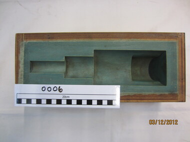
Valve stem mould
Used to make casting moulds for the Otway Water Supply System in the 1980s. Used in conjunction with scour valve mould, Wf mould and high pressure scour valve mould (casting) watermainsUsed in the manufacture of spare parts for the Otway Water Supply pipelinevalve stem casting mould in plywood boxwatermains in black textaotway region, water supply, pipelines -
 Kiewa Valley Historical Society
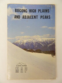
Map - Bogong High Plains & Adjacent Peaks x2, 1976
This map was produced as a result of the 'pressure from walkers' who are interested in climbing the accessible peaks on the Bogong High Plains. Places, huts and rivers are named and indexed. Contours are not given. Heights of mountains are in metres.The Bogong High Plains is a popular walking area and a National Park. This map identifies the mountains and peaks in the area at the time of publication. Some of the huts have since been destroyed by fire and Mt Niggerhead has since been renamed to Jaithmathang.Blue and white cardboard folded in half containing a folded black and white map of Bogong High Plains and Adjacent Peaks with index.bogong high plains. mountains. bushwalkers. walking. map. national park. recreation. cycling. tourism -
 Kiewa Valley Historical Society
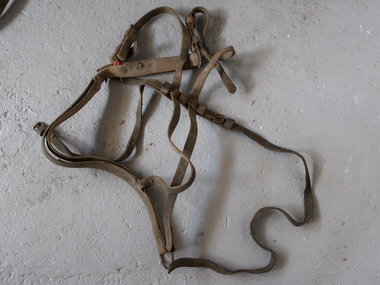
Breeching Harness, Horse Equipment
A harness distributes pressure over a large area of the horse. The breeching harness can be used for a single horse, a pair, or in a larger team but only for the pair closest to the vehicle as only they have control of the vehicle.Used by residents in the Kiewa Valley prior to motorised vehicles.Goes around the horse's haunches ie. back end of the horse. Allows the horse to slow a vehicle or hold it back when going down the hill. Connects to the shafts. Leather with steel buckles and rivets and chains.horse equipment, breeching harness -
 Kiewa Valley Historical Society
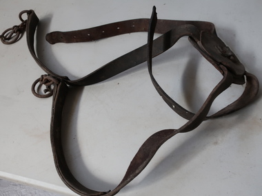
Breeching Straps, Horse Equipment
A harness distributes pressure over a large area of the horse. The breeching harness can be used for a single horse, a pair or in a larger team but only for the pair closest to the vehicle as only they have control of the vehicle.Used by residents in the Kiewa Valley prior to motorised vehicles.The harness has a round bit of leather that sits on top of the hind quarters and it connects to or is part of the breeching harness. Also connects to the crupper (the strap that hooks under the tail). Leather with steel buckles and chainbreeching straps, breeching harness, horse equipment -
 Wannon Water
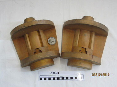
Wf valve mould, Mould
Used in the manufacture of spare parts for the Otway Water supply pipeline in the 1980s. Used in conjunction with scour valve mould, valve stem mould and high pressure scour valve mould (casting) watermainsUsed to manufacture spare parts in the 1980sWooden casting mould in 2 piecesotway region, pipelines, water supply -
 Wannon Water
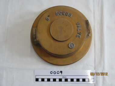
3" Scour valve mould, Valve mould
Used in the manufacture of spare parts for the Otway Water supply pipeline in the 1980s. Used in conjunction with scour valve mould, valve stem mould and high pressure scour valve mould (casting) watermains Used to manufacture spare parts in the 1980swooden casting mould3" Scour Valve in silver raised lettering WF Logo in silver and raise In black texta - DEMAC 4 off C.I.otway region, pipeline, water supply -
 Orbost & District Historical Society
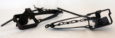
rabbit traps, First half 20th century
During the Great Depression from 1929 to 1932, rabbit trapping was a means of survival for many people. Rabbits provided meat and pelts which were sold for making felt hats such as the Akubra. Rabbit populations are controlled in the 21st century by poisoning, destroying or 'ripping' burrows (warrens), biological control with rabbit haemorrhagic disease and myxomatosis, and by shooting. Rabbit-proof fences also prevent the spread of rabbits into some areas. (ref. Powerhouse Museum) Steel-jawed rabbit traps were widely used in urban and rural Australia from 1880 to 1980. This trap is symbolic of the battle that Australians have waged against burgeoning rabbit populations for over a century. Rabbits cause enormous damage to Australian soils and biodiversity. The introduction of rabbits to this country was an environmental disaster.Two iron rabbit traps. Each consists of a pair of jaws held closed by spring tension and a triggering mechanism. When the trap is triggered the jaws close over the top of the bridge, plate and tongue mechanism that is designed to trigger the trap. A chain is attached by a hook on the bent end of the trap's spring with a long steel spike looped over the last link of the other end of the chain. The trap is designed so that the metal jaws snap shut against each other when the trap is activated by the application of weight to the pressure plate. In use, traps are set with open jaws, buried lightly just below the surface of the earth. When an animal steps on the pressure plate, the jagged teeth of the jaws snap around the animal's leg, usually breaking bone and sinew. Thus the animal is immobilised.rabbits rural trapping -
 Orbost & District Historical Society
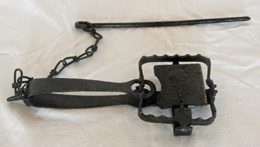
rabbit trap, first half 20th century
During the Great Depression from 1929 to 1932, rabbit trapping was a means of survival for many people. Rabbits provided meat and pelts which were sold for making felt hats such as the Akubra. Rabbit populations are controlled in the 21st century by poisoning, destroying or 'ripping' burrows (warrens), biological control with rabbit haemorrhagic disease and myxomatosis, and by shooting. Rabbit-proof fences also prevent the spread of rabbits into some areas. (ref. Powerhouse Museum) This trap was used in the Orbost district. Steel-jawed rabbit traps were widely used in urban and rural Australia from 1880 to 1980. This trap is symbolic of the battle that Australians have waged against burgeoning rabbit populations for over a century. Rabbits cause enormous damage to Australian soils and biodiversity. The introduction of rabbits to this country was an environmental disaster.A rusted iron rabbit trap which consists of a pair of jaws held closed by spring tension and a triggering mechanism. When the trap is triggered the jaws close over the top of the bridge, plate and tongue mechanism that is designed to trigger the trap. A chain is attached by a hook on the bent end of the trap's spring with a long steel spike looped over the last link of the other end of the chain. The trap is designed so that the metal jaws snap shut against each other when the trap is activated by the application of weight to the pressure plate. In use, traps are set with open jaws, buried lightly just below the surface of the earth. When an animal steps on the pressure plate, the jagged teeth of the jaws snap around the animal's leg, usually breaking bone and sinew. Thus the animal is immobilised. rabbit-trap rural -
 Federation University Historical Collection
Photograph - Black and white photograph, Ballarat School of Mines Model Steam Engine
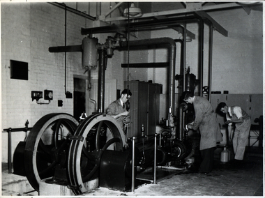
The Davey Paxman Experimental Steam Engine was purchased as the result of a bequest from Thomas Bath. The 'substantial sum' was used to build an Engineering Laboratory. The Ballarat School of Mines Council minutes of 08 November 1901 record: - Plans for [the] proposed building were submitted ... and ... it was resolved that a temporary building for an Engineering Laboratory be put up.' This laboratory, as an existing building, is first mentioned in the Ballarat School of Mines President's Annual Report of 1901, presented on 28 February 1902, reporting 'the erection of a building 67ft long by 33 ft wide' This report also lists all the equipment that would be accommodated in the Engineering Laboratory, including the experimental steam engine and boiler. The experimental Davey-Paxman steam engine arrived in Ballarat towards the end of 1902. The Engineering Laboratory was opened on 14 August 1903 by His Excellency Sir Sydenham Clarke. This engineering laboratory remained in use till about 1945. By 1944 preparations were under way at the Ballarat School of Mines to expand existing facilities, to be ready for the influx of returned soldiers. A new Heat Engines laboratory was built, this time of brick construction, replacing the previous corrugated-iron shed. In the early stages the steam engine was used to drive an overhead transmission shaft for machinery in the adjacent workshop. Later the steam engine was moved to a space that became the Heat Thermodynamics Laboratory. At the end of 1969 the engine was relocated to the Thermodynamics Laboratory at the then Ballarat Institute of Advanced Education (BIAE) Mt Helen Campus. It was donated to Sovereign Hill in 2006. According to the research of Rohan Lamb in 2001 around five experimental steam engines were made by Davey Paxman, and three of these had similar configuration to the Ballarat School of Mines Steam Engine, however, each of these was also unique with different valve arrangements. The list, which was on a scrap of paper in a folio held in the Essex Archives, confirmed that one was sent to India. The Ballarat steam engine can be dated to late 1901 to early 1902. Zig Plavina was responsible for moving the steam engine to Mount Helen, and worked on it as a technician for many years. He observed the following: * The condenser is driven by the low pressure engine. * The following arrangements are possible: i) the high pressure engine alone, exhausting to atmosphere. Condenser not used, crankshaft flanges not coupled. ii) crankshafts coupled, mains pressure (120 psi) steam supplied to high pressure engine, partially expanded steam delivered to low pressure engine (Tandem operation). Choice available re exhaust steam: either to the condenser or to atmosphere. iii) crankshafts not coupled, reduced pressure steam supplied to low pressure engine. Exhaust steam - either to the condenser or to atmosphere. * Valve arrangement - a choice of Pickering cut-off or throttle governor. On low pressure engine - throttle governor only.Black and white photograph of the Davey Paxman Experimental Steam Engine. On the brake is returned serviceman Norman WIlliam Ludbrook (Diploma Electrical Engineering, 1952). Far right is Roy E. Mawby (Diploma Electrical Engineering, 1950)steam engine, model steam engine, davey paxman, electrical engineering, laboratory, scientific instrument, norman ludbrook, norman william ludbrook, roay mawby, roy e. mawby -
 Federation University Historical Collection
Photograph - Photograph - Black and white, Ballarat School of Mines Model Steam Engine
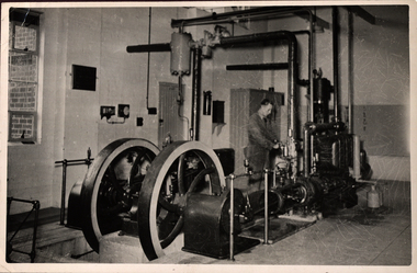
The Davey Paxman Experimental Steam Engine was purchased as the result of a bequest from Thomas Bath. The 'substantial sum' was used to build an Engineering Laboratory. The Ballarat School of Mines Council minutes of 08 November 1901 record: - Plans for [the] proposed building were submitted ... and ... it was resolved that a temporary building for an Engineering Laboratory be put up.' This laboratory, as an existing building, is first mentioned in the Ballarat School of Mines President's Annual Report of 1901, presented on 28 February 1902, reporting 'the erection of a building 67ft long by 33 ft wide' This report also lists all the equipment that would be accommodated in the Engineering Laboratory, including the experimental steam engine and boiler. The experimental Davey-Paxman steam engine arrived in Ballarat towards the end of 1902. The Engineering Laboratory was opened on 14 August 1903 by His Excellency Sir Sydenham Clarke. This engineering laboratory remained in use till about 1945. By 1944 preparations were under way at the Ballarat School of Mines to expand existing facilities, to be ready for the influx of returned soldiers. A new Heat Engines laboratory was built, this time of brick construction, replacing the previous corrugated-iron shed. In the early stages the steam engine was used to drive an overhead transmission shaft for machinery in the adjacent workshop. Later the steam engine was moved to a space that became the Heat Thermodynamics Laboratory. At the end of 1969 the engine was relocated to the Thermodynamics Laboratory at the then Ballarat Institute of Advanced Education (BIAE) Mt Helen Campus. It was donated to Sovereign Hill in 2006. According to the research of Rohan Lamb in 2001 around five experimental steam engines were made by Davey Paxman, and three of these had similar configuration to the Ballarat School of Mines Steam Engine, however, each of these was also unique with different valve arrangements. The list, which was on a scrap of paper in a folio held in the Essex Archives, confirmed that one was sent to India. The Ballarat steam engine can be dated to late 1901 to early 1902. Zig Plavina was responsible for moving the steam engine to Mount Helen, and worked on it as a technician for many years. He observed the following: * The condenser is driven by the low pressure engine. * The following arrangements are possible: i) the high pressure engine alone, exhausting to atmosphere. Condenser not used, crankshaft flanges not coupled. ii) crankshafts coupled, mains pressure (120 psi) steam supplied to high pressure engine, partially expanded steam delivered to low pressure engine (Tandem operation). Choice available re exhaust steam: either to the condenser or to atmosphere. iii) crankshafts not coupled, reduced pressure steam supplied to low pressure engine. Exhaust steam - either to the condenser or to atmosphere. * Valve arrangement - a choice of Pickering cut-off or throttle governor. On low pressure engine - throttle governor only.Black and white photograph of the Davey Paxman Experimental Steam Engine installed at the Ballarat School of MInes. steam engine, model steam engine, davey paxman, thomas bath, experimental steam engine -
 Federation University Historical Collection
Photograph, Ballarat School of Mines Davey Paxman Experimental Steam Engine, c1902
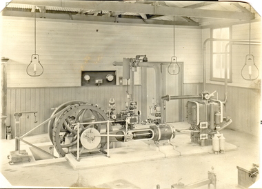
The Davey Paxman Experimental Steam Engine was purchased as the result of a bequest from Thomas Bath. The 'substantial sum' was used to build an Engineering Laboratory. The Ballarat School of Mines Council minutes of 08 November 1901 record: - Plans for [the] proposed building were submitted ... and ... it was resolved that a temporary building for an Engineering Laboratory be put up.' This laboratory, as an existing building, is first mentioned in the Ballarat School of Mines President's Annual Report of 1901, presented on 28 February 1902, reporting 'the erection of a building 67ft long by 33 ft wide' This report also lists all the equipment that would be accommodated in the Engineering Laboratory, including the experimental steam engine and boiler. The experimental Davey-Paxman steam engine arrived in Ballarat towards the end of 1902. The Engineering Laboratory was opened on 14 August 1903 by His Excellency Sir Sydenham Clarke. This engineering laboratory remained in use till about 1945. By 1944 preparations were under way at the Ballarat School of Mines to expand existing facilities, to be ready for the influx of returned soldiers. A new Heat Engines laboratory was built, this time of brick construction, replacing the previous corrugated-iron shed. In the early stages the steam engine was used to drive an overhead transmission shaft for machinery in the adjacent workshop. Later the steam engine was moved to a space that became the Heat Thermodynamics Laboratory. At the end of 1969 the engine was relocated to the Thermodynamics Laboratory at the then Ballarat Institute of Advanced Education (BIAE) Mt Helen Campus. It was donated to Sovereign Hill in 2006. According to the research of Rohan Lamb in 2001 around five experimental steam engines were made by Davey Paxman, and three of these had similar configuration to the Ballarat School of Mines Steam Engine, however, each of these was also unique with different valve arrangements. The list, which was on a scrap of paper in a folio held in the Essex Archives, confirmed that one was sent to India. The Ballarat steam engine can be dated to late 1901 to early 1902. Zig Plavina was responsible for moving the steam engine to Mount Helen, and worked on it as a technician for many years. He observed the following: * The condenser is driven by the low pressure engine. * The following arrangements are possible: i) the high pressure engine alone, exhausting to atmosphere. Condenser not used, crankshaft flanges not coupled. ii) crankshafts coupled, mains pressure (120 psi) steam supplied to high pressure engine, partially expanded steam delivered to low pressure engine (Tandem operation). Choice available re exhaust steam: either to the condenser or to atmosphere. iii) crankshafts not coupled, reduced pressure steam supplied to low pressure engine. Exhaust steam - either to the condenser or to atmosphere. * Valve arrangement - a choice of Pickering cut-off or throttle governor. On low pressure engine - throttle governor only. Black and white photograph of an experimental steam engine which was produced for the Ballarat School of Mines. It was designed for experimental purposes, such as testing of efficiency, etc. The laboratory which housed the steam engine was lit with gas lighting. davey paxman experimental steam engine, model steam engine, davey paxman, steam, thomas bath, thermodynamics -
 Lakes Entrance Regional Historical Society (operating as Lakes Entrance History Centre & Museum)
Domestic Object - Flower Press
2 x 205 cm wooden plates aligned together by threaded bolts in each corner, corners have been rounded, butterfly nuts on each bolt used to apply pressure between both platesWooden flower press, 2 wooden plates held together with bolt in each corner, used to press flowershandcrafts, equipment -
Surrey Hills Historical Society Collection
Archive - Vertical file, Chatham Primary School
Chatham Primary School opened in August 1927 following local pressure for an additional school. Balwyn, Mont Albert and Surrey Hills schools were all experiencing overcrowding following population growth after WW1.A vertical file of information related to Chatham Primary School: 1. Correspondence regarding establishment of the school – all are copies: • Letter from Amy Brown to Secretary of Chatham School Committee (undated) relating to correspondence regarding the establishment of the school • Letter from Education Department to Mr. A.R. Brown, 17.5.1923. • Letter from Department of Public Works to Mrs. Amy R. Brown, 2.10.1923. • Letter from Education Department to Mr. A.R. Brown, 2.11.1923. • Letter from A. Brown to Education Department ?, 7.11.1923. • Letter from E.W. Greenwood, MLA, State Parliament House to Mr. A.R. Brown, 8.11.1923. • Letter from E.W. Greenwood, State Parliament House to Mr. A.R. Brown, 19.11.1923. • Letter from Department of Public Works to Mrs. Amy R. Brown, 5.12.1923. • Letter from Education Department to Mrs. A. Brown, 8.12.1923. • Letter from A. Brown to Mr. Greenwood, 26.7.1925. • Letter from E.W. Greenwood, State Parliament House to Mrs. A. Brown, 14.3.1925. • Letter from E.W. Greenwood, State Parliament House to Mrs. A. Brown, 15.7.1925. 2. Letter from E.W. Greenwood, State Parliament House to Mrs. A. Brown, 16.11.1925. 3. Letter from Department of Public Works to Mrs. A. R. Brown, 10.11.1926. 4. Letter from E.W. Greenwood, State Parliament House to Mrs. A. Brown, 2.3.1923. 5. Letter from E.W. Greenwood, State Parliament House to Mrs. A. Brown, 3.6.1927. 6. Letter from E.W. Greenwood, State Parliament House to Mrs. A. Brown, 29.6.1927. 7. 2 Mr. Harbert’s account for Shelter Shed, Chatham State School, (undated), (1 page). 8. 4 copies of newspaper cuttings: 9. ‘Masts tell Edina’s history’, Herald, 4.5.1931, 10. ‘Edina to have holiday on 80th birthday’, Argus, 4.5.1934, 11. ‘Edina’s birthday tomorrow’, Age, 4.5.1934, 12. ‘Old lady of the sea has a birthday’, Star, 4.5.1934 (1 page). 13. ‘The story of the steamship “Edina” a wonderful veteran of the seas’, The Meccano Magazine, A.R. Prince, December, 193 ? (1 page). 14. ‘Ponsford and schoolboys’, (paper and date unknown), (2 pages). 15. Program for ‘Trial by jury’, 16.11.1929 (1 page). 16. ‘What was the joke that the Governor told?’, paper unknown, 5.5.1931 (1 page). 17. ‘History in school flag’, paper and date unknown (1 page). 18. Lists of girl and boy dux 1928 – 1944 (1page). 19. Chatham School 4314 notes (undated) (3 pages). 20. Extracts from Box Hill Reporter, 1927-9, from Alan Holt collection (1 page). 21. Empire day celebrations in Surrey Hills in 1930s, notes from Matt Bowen, 1983 (1 page). 22. Extracts from Box Hill Reporter 1927-8 (1 page). 23. Vision and realisation, 1973 Education Department : Port Phillip Eastern Region: 4314 Chatham notes by H.H. Singleton (1 page). 24. ‘Bell has historic appeal’, paper unknown, c. 1985 (1 page). 25. Background information on the SS 'Edina' bell, Adrian Peniston-Bird, Principal of Chatham Primary School, 1982 (1 page). 26. ‘It’s there for another fifty years’, October, 1985. See also ‘Chatham past and present, a patchwork of people’. (1 page). 27. ‘Miss Marie George’, SHNN No. 40, June/July, 1989 (1 page). 28. ‘Chatham Primary School – a community within the community’, SHNN No. 56, Feb/March, 1992 (1 page). 29. ‘Chatham Primary School – another exciting year begins’, SHNN No. 68, Feb./March, 1994 (1 page). 30. ‘Chatham plans a big reunion’, SHNN No. 77, Aug./Sept. 1995 (1 page). 31. ‘In search of the past’, Progress Press, 15.5.1996 (1 page). 32. ‘Chatham primary’, SHNN No. 82, June/July, 1996 (1 page). 33. ‘Happy Birthday, Chatham Primary’, SHNN No. 84, Oct./Nov. 1996 (1 page). 34. Chatham School Fathers Club, SHNN No. 83, Aug./Sept. 1996 (1 page). 35. Notes by Doug Iversen, 18.7. year unknown, (1 page). 36. Advertisement for Chatham Primary School celebrating 70 years: ‘Take a walk down memory lane’, 10.9.1996, paper unknown (1 page). 37. Chatham Primary School invitation to 70th year celebration – Sat. 19.10.1996 (1 page), AND Back to Chatham (1 page). 38. Flyer: Chatham Primary School Reunion Celebrating 70 years 19.10.1996 (1 page, 2 copies). 39. Program ‘Welcome to Chatham Primary School No. 4314 70th celebration’, undated (1 page, 2 copies). 40. Chatham History trail, undated (1 page). 41. Drawing of Chatham Primary School, David Williams, 1995 (1 page). 42. ‘Seems like yesterday’ 1998, paper unknown (1 page). 43. ‘Schools and the environment’, SHNN No. 98, Feb./March, 1999 (1 page). 44. ‘School praises retiring head’, by Kate Morris, 19.6.2000, paper unknown (1 page). 45. “Chatham’s class of ‘30” by Meg Freeman, Progress Press, c. July, 2000 (1 page). 46. ‘Recalling a class act’, Progress Press, c. August, 2000 (1 page). 47. List of students enrolling in 1930 (2 pages). 48. ‘Boy in man’s shoes’, Progress Press, 21.8.2000 (1 page). 49. Chatham Foundation Day Lunch invitation 31.7.2000, (with contact details of former students on the back, written by Ken Hall) (1 page). 50. ‘An invitation – Chatham Primary plans for its 75th birthday’, SHNN No. 118, June/July, 2002 (1 page). 51. 75th birthday assembly – August 1st 2002 (1 page). 52. ‘Chatham lands special garden’ (paper and date unknown, possibly Progress Leader) (1 page). 53. ‘Chatham Primary celebrates specialist programs’, SHNN No. 184, June/July 2013 (1 page). 54. ‘City’s sustainable schools awarded this month’, Boroondara Bulletin, April, 2013 (1 page). 55. ‘Chatham Primary walks to win’, SHNN No. 189 March/April 2014 (1 page). 56. ‘School builds pathway to greater sustainability’, Progress Leader, 15.9.2015 (1 page). 57. ‘Schools embrace need for class action’, Age, 7.11.2016 (1 page). 58. Advertisements for 2017 grand fair 4th March, 2 designs (3 pages including 2 copies of one). 50. A history of Chatham Primary School, golden jubilee edition 1977 (9 pages with covers). 51. Photo of Mrs. Frances Le Couteur receiving a gift at Chatham Primary School, golden jubilee 1977 (1 page). 52. ‘Thank you’ letter to editor from Mrs. Frances Le Couteur (paper unknown), 1977 (1 page). 53. Letter from Chatham School No. 4314 to Mrs. Ethel Cerini, 10.2.193 ? (1 page). 54. Programme for concert held in the 1930s (source possibly Jocelyn Hall) (1 page). (mrs) amy brown, e w greenwood, albert harbert, s s edina, matt bowen, adrian peniston-bird, marie george, reunions, doug iverson, david williams, meg freeman, frances le couteur, ethel cerini -
 Bendigo Military Museum
Souvenir - SOUVENIRS, FRAMED
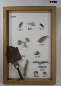
Souvenirs collected from the Battlefields of Gallipoli, Pozieres and Fromelles by PETER SIMMONS A43266 (RAAF) Souvenirs - collection of 17 items from the battlefields of Gallipoli, Pozieres and Fromelles. Items include bullet casing, shrapnel, equipment, items and stores, Adhered to backing cardboard with a putty like, pressure sensitive adhesive (Blu Tack). Item labels - black ink on white adhesive paper labels. Frame - timber, with deep edge, cardboard backing board.Handwritten - black ink on white adhesive labels top L to R. "BULLET CASING/ FOUND GALLIPOLI/ 2009" "REMAINS OF RUM JAR, GALLIPOLI" "GALLIPOLI SHRAPNEL" 2nd Row L to R "PEBBLES FROM ANZAC COVE/ 2009" "SHRAPNEL/ FROM/GALLIPOLI 2009" 3rd Row L to R "AUSTRALIAN/TRENCHING TOOL/ FROMELLES 2009" "STONE FROM/ UNDER/ HILL 60 YPRES" 4th Row "BULLET CASING/ POZIERES/ BATTLEFIELD 2009" 5th Row "SHRAPNEL/ FROMELLES/ FOUND 1993" 6th Row L to R "CANTEEN/ HANDLE/ FROMELLES" "AUSTRALIAN/ EQUIP BUCKLE/ FROMELLES BATTLEFIELD/1993" "END FROM EQUIP/ STRAP/ FROMELLES/FRANCE" souvenirs, ww1, gallipoli, battlefields -
 Kiewa Valley Historical Society
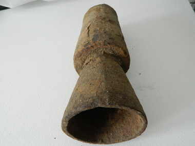
Tuyere Pipe, circa mid to late 1900's
This tuyere (word from French origin) was used by professional blacksmiths and or cattlemen before and during the Kiewa Hydro Electricity Scheme was being constructed. The need to use a furnace or forge in the shaping of metal rods, horse shoes and pipes is both a rural necessity and a construction, on site requirement. The "inventiveness" of cattlemen and construction workers to produce metal objects not available "off the shelf" is one of the inherent traits not only of rural self sufficiency but in the "pioneer" days of rural isolation one of survival.This tuyere is of great significance to the Kiewa Valley and its regions because it highlights one of the greatest strengths of the rural (especially isolated) life and its folk living there, and that is the great human factor of adaptability and survival techniques in sometimes harsh and demanding environmental circumstances. The inventiveness and the attitude, "she'll be right mate", demonstrates life on the land where specialised blacksmith activities can be found in non "professionals" because of the fact that "someone" has to do the job. This is one of the differences between country "rural" life and that found in cities and larger towns.This iron cone shaped tuyere has a small hole (diamenter 25mm) starting within an ever enlarging cone (amplification of the air pressure going through) delivering varying hot or extremely hot air into a furnace or hearth which intensifies the heat to allow the "shaping" of metal objects. The larger "flared" cone extension allows for the directed air to be spread and not concentrated.blacksmith tool, tue, bellows, fashioning metal, forge manufacturing process -
 Kiewa Valley Historical Society
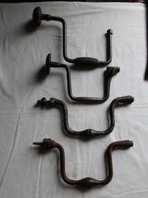
Braces for Hand Drilling x4
Very old. Ref. Pages 6 and 7 Tools for all Trades Catalogue. The braces vary in quality (strength) depending on what materials are used to make them.The brace is a hand operated tool for boring holes in wood, consisting of a crank-shaped turning device. The brace that grips and rotates the hole-cutting tool, the bit.Used by woodworkers in the Kiewa Valley.Vintage hand drill braces. All different and not all complete. Made of cast iron, steel with wooden handles. The drills fit into one end of the brace which is turned to make a drilling motion. A brace is a hand tool used with a bit (drill bit or auger) to drill holes, usually in wood. Pressure is applied to the top while the handle is rotated.brace and bit, woodwork, hand drilling -
Dunkeld Museum Inc.
Boots, Riding
Brown leather riding boots, with hourglass shaped motif tooled 7 stitched on both sides of upper leg. Leather sole with separate layer of leather to form shoe upper stitched to leg section. Wooden inserts are positioned inside the leg upper sections with separate wedge shaped insert that can be withdrawn or inserted to apply pressure to retain leg shape.boots -
 Kiewa Valley Historical Society
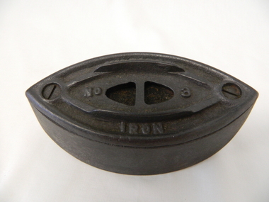
Iron Hand, 1867 to 1871
This is size one of three sizes (Mrs Potts) irons available in the late 1800s and early 1900s which were used for (press) ironing clothes etc. using wood or coal based heaters. The majority of these irons would have been placed on top of wood or coal fuelled stoves. They survived longer in isolated outback regions where electricity had not been connected. The weight of these irons was intentionally heavy so as to press the clothes etc. neatly. These irons were used in an era where stiff collars and creases in particular types of clothing was essentially a social requirementHistorically these irons fulfilled a particular function that was the norm in isolated or semi isolated country locations i.e., ironed clothes and linen.The iron was heated by using locally acquired wood in a cast iron stove or "pot Belly". It would be placed on top of the stove but not directly in the flames. Cities and larger towns had professional laundry and pressing shops. In smaller towns and homesteads, wives and relatives would use these heavy irons which required strong arms. In middle and higher levels of society these irons would be used by maids or nannies. Their use was a necessity, to conform to the social requirements of acceptable appearances in that all clothing worn had been "pressed" clean. In the Kiewa Valley the majority of these irons would have been used by mothers or relatives. Men would hardly have used these irons as society labelled this type of activity as "women's work"This double pointed, heavy and solid cast iron, is a Mrs Potts No.3 type. It does not have a handle. It was used to iron clothes. Open cavity on top for handle (not included) Note: one end is pointed up to allow the natural weight of the iron to increase the pressure at any of the "hard to press" spots or emphasizing required creases. see KVHS 0368 for No. 1 ironMrs Potts No. 3house hold, ironing, domestic, pressing, clothes appliance -
 Geoffrey Kaye Museum of Anaesthetic History
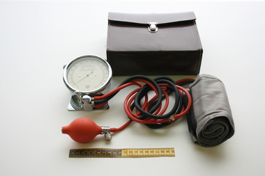
Equipment - Oscillotonometer, von Recklinghausen
This oscillotonometer was owned by Dr. Herbert Claus Newman, an Anaesthetist who gained his diploma in Anaesthetics in 1956. Dr Newman served in the Vietnam War and was also one of over 50 of Australia's medical professionals who signed a joint statement in 2004 condemning the Federal Government for committing Australian troops to the Iraq war.Brown leather case with silver clasp and brown leather handle. Case contains Dr. von Recklinghausen Scala Alternans Oscillotonometer – a round silver pressure gauge with paper scale and needle point reader. The silver valve and lever at the bottom of the gauge connects black and orange rubber tubing to the grey linen arm cuff rolled closed with Velcro and a rubber inflation bulb.Yellow sticker on top of case in yellow type: H. NEWMAN Printed on face of gauge: Oscillotonometer / n. Dr. von Recklinghausen / "SCALA ALTERNANS" / 6585868 / S|K Printed on scale near zero reading: mmHg Printed on scale near highest reading: mm Hg = Torr Printed on scale is numbers 0 to 300 in increments of 20 Stamped on reverse of valve: 148blood pressure, oscillotonometer, dr. von recklinghausen, scala alternans, newman, h., newman, herbert claus, vietnam war -
 Forests Commission Retired Personnel Association (FCRPA)
Driptorch - Firebug (hand held), c 1985
The origins of the humble handheld driptorch have been lost in time. They are widely used for ignition in controlled burning operations in forest and grasslands. The “Pacific Forester“ with its short central wand and somewhat leaky ball-valve was made by the American Wajax company in the 1940s. The Pacific Forester is slightly different in design from the more robust and common “Panama” driptorch first manufactured in 1933 and used extensively by Queensland cane farmers. The Panama is closely related to the current “Firebug” used in Victoria which is manufactured by Rodney Industries in Brisbane and has an offset wand design which gives it good balance. The fuel is a mixture of petrol and diesel and every FCV District had their own closely-guarded secret formula ... 2:1, 3:1, 1:1, 4:1 or 3:2 ratio. There was also the choice of 91, 95 or 98 octane petrol mixed with summer or winter diesel. Occasionally some of the old Avgas or Jet-A1 lying around the depot was added with a splash of engine oil to make the mixture stick to the fuel to be ignited. The fuel mixed also varied between autumn or spring, heathland, mixed forest, or high-intensity slash burnsCommon driptorch used throughout AustraliaDrip torch with handle Wand has loop and valve. The loop is designed to assist with even flow of fuel which flows out onto the burning head of the wand. Pressure equalising value in top of aluminum fuel container which holds 4 litres of burner mix. Gravitational feed of the driptorch allows the unit to drip fire, making it simple and quick to operate. Instructions for use. CF+L written with texta pen.bushfire -
 Kiewa Valley Historical Society
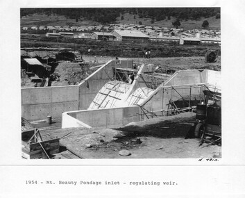
Photograph - Folder of Photographs – Photocopied set of 10 black and white photographs (pages 29 - 38) from the display folder put together by KVHS to document life on the Kiewa Valley Hydro-electric Scheme
Although the Kiewa Hydro-Electric Scheme was first proposed in 1911, construction did not commence until 1938. As part of the push to cut electricity costs and diversify supply, the Victorian Government (circa 1930) initiated the conversion from primarily brown coal supply to hydro – electricity. Field investigations during the 1940’s resulted in a new proposal for a scheme that had more than double the capacity of the 1938 scheme. The Kiewa Hydroelectric Scheme became the largest scheme of its kind in the State Of Victoria and the second largest scheme in Australia. The number of personnel involved in the planning and construction of the scheme increased dramatically. During the late 1940’s, most activity centred around the construction of the West Kiewa Power Station, Rocky Valley Reservoir, McKay Creek Power Station and the Bogong Creek Aqueduct.A common thread across all the larger hydro scheme constructions was the need for workers, both qualified and unqualified who came from around the world seeking a new life for themselves and their families. New accommodation and facilities were required for the army of workers engaged in construction in often remote and wild areas. The SEC had a high demand for timber, and set up the first of a number of sawmills at Bogong Creek in 1939 and set up the first hardwood logging in the headwaters of the Kiewa River. These new ‘towns’ such as Mt Beauty and Bogong, survived, serving the needs of operational personnel and their families, and expanding with growth of new industries. Mount Beauty, and to a lesser extent Bogong, are among these places. Large A3 size spiral bound display folder containing 21 pages of photocopied black and white photographs of various aspects of the early days of the Kiewa Valley Hydro-electric scheme including equipment, various work sites and photographs of workers and their families. 1-Mt Beauty Pondage inlet-Regulating weir 2-Langfords Gap Basalt Hill-Tunnel in quarry face.3-Rocky Valley Camp-from Engineering Office 4-Basalt Hill tunnel portal 5-No 1 Pressure Shaft Works Bench 6-No 1 Power Station 7-Overturned haulage wagons on the side of an embankment 8- Group of workers dressed in wet weather gear inside a tunnel 9-Workmen and vehicle in tunnel 10-Howman’s Gap campsite at 4,150 feet 1-1954 – Mt Beauty Pondage inlet – Regulating weir Page number 29 2-28/10/54 – Langfords Gap Basalt Hill – Tunnel in quarry face K7860 Page number 30 3-STATE ELECTRICITY COMMISSION OF VICTORIA Date: 17.8.55 Time: No K8132 Kiewa Hydro Electric Works ROCKY VALLEY CAMP – FROM ENGINEERING OFFICE Page number 31 4-28/10/54 – Basalt Hill tunnel portal K7859 Page number 32 5-No.1 Pressure Shaft Works Bench 5.7.56 Page number 33 6- No. 1 Power Station 26.4.59 Page number 34 7- No markings Page number 35 8-No markings (Wooden board on ground printed with - POLAR A.N.GELATINE DYNAMITE “75” DE 28.8.40) Page number 36 9-No markings Page number 37 10-Howman’s Gap campsite at 4,150 feet Page number 38 secv; kiewa hydro electric scheme; mt beauty; bogong; construction area -
 Cheese World Museum
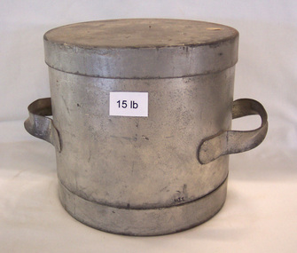
Cheese mould
Possibly part of the Uebergang collection. The moulds are placed under pressure during the maturation process with excess moisture being forced out through the holes in the lid. This is one of a set of moulds with a size range 5lb, 10lb, 15lb, 20lb, 40lb, 80lb.Round galvanised steel cheese hoop with strap handles soldered to the sides. The round lid has 6 holes. -
Unions Ballarat
WJ McAdam: "Labor Memoirs, Ballarat", William J McAdam, circa 1960s
W.J. McAdam was a former union organiser (Ballarat Municipal Employees section of the Shop Assistants and Textile Workers Union). He is a past president and secretary (on two occasions) of Trades Hall, Ballarat. "Labor Memoirs, Ballarat": #Ballarat North Railway Workshops History #Preferential voting at elections #History of the White Swan Dam Project (1 vol) The White Swan Dam was completed in the 1950s. Ballarat North Railway Workshops were opened in 1917 after political pressure to decentralise railway workshops. The White Swan Dam was completed in the 1950s. Ballarat North Railway Workshops were opened in 1917 after political pressure to decentralise railway workshops. Relevant to Ballarat employment opportunities, history of preferential voting and history of the White Swan Dam Project. 2017 is the centenary of this important outcome for the City of Ballarat. Paper (1 volume) btlc, ballarat trades hall, ballarat trades and labour council, wj mcadam, labor memoirs, preferential voting, elections, white swan dam project, textiles, textile, clothing and footwear union, white swan reservoir, railways, voting, ballarat north railway workshops -
 Parks Victoria - Point Hicks Lightstation
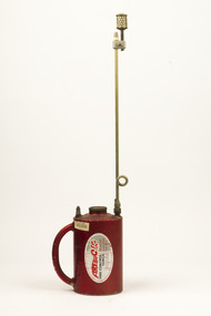
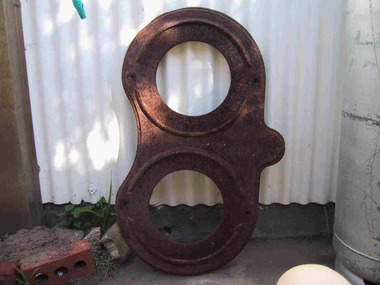
Stand, pump & tank
Was the stand for a Chance Brothers air & oil containers fitted with pump handle & pressure gauges.This type of installation was once common and relied on the lightkeeper having to pressurise the cylinders manually at regular intervals throughout the hours of darkness. The oil was fed under pressure to the burner mantle. It is all that remains of an air and kerosene oil tank installation, with each rounded side formerly supporting a heavy iron tank. The containers would have been fitted with a pump handle and pressure gauges. An intact assemblage is displayed in the AMSA offices, Canberra with a text that explains ‘This type of installation was once common and relied on the lightkeeper having to pressurise the cylinders manually at regular intervals throughout the hours of darkness’.The system involved vaporising kerosene under pressure and mixing it with air and then burning the vapour to heat an incandescent mantle. The use of kerosene as a fuel to light the lantern became the most common system of illumination from the 1860s after the oil industry in the United States began to develop. The kerosene vapour burner was created in 1901 by British inventor Arthur Kitson (1859-1937) and perfected by Chance Bros for burning a more intense light in their renowned lenses. The lamp had to be watched throughout the night in case a mantle broke, and the tanks needed to be maintained by hand-pumping each hour or so. The Point Hicks lantern was initially lit by a six-wick Trinity house kerosene burner. This was replaced by the more efficient and brighter 55mm vaporised kerosene mantle burner in 1905, and the tank stand is probably original to this apparatus. Electricity eventually replaced kerosene at Point Hicks in 1964 making the tank installation obsolete, and the last kerosene system in an Australian lighthouse was replaced in 1985. Gabo Island Lightstation has a pair of tanks that are not attached to the optical system and are no longer in the lighthouse. They are also missing the pressure gauges that were formerly attached to the top of each cylinder. An intact tank assemblage is displayed at the Cape Schanck Lighthouse Museum it is detached and not original to the lighthouse. Although corroded, the remnant Point Hicks tank stand has first level contributory importance to the lightstation. It is significant for its provenance and historical value as part of the Chance Bros vaporised kerosene burner introduced in 1905 to intensify the light and improve the efficiency of the system. The rusted iron stand rests on four short legs and is shaped like a pair of spectacles. -
 Creswick Campus Historical Collection - University of Melbourne
Equipment, WA Webb Ltd, 1914-1933
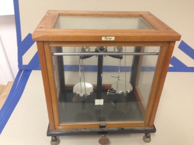
The distributors mark is found at the bottom of the scales on a white plaque.When the levers are realised it allows the pans to rest, reducing the pressure on the knife-edges. A plaque at the top reads Bybryt. A plaque at the back reads �War Finish�, a typical mark for products for miiltary use or for austere timesPharmacy Scales in CabinetWar Finish -
 Geoffrey Kaye Museum of Anaesthetic History
Photograph
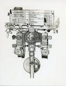
The McKesson Nargraf anaesthetic record was introduced in 1930, created by Dr Elmer I. McKesson.Black and white photograph of a drawing of the head of a McKesson Nargraf anaesthetic record, Model H. The view is from the top looking down onto the machine. There are two pressure gauges on either side of the round central component, with controls for oxygen, nitrous oxide, ethylene and carbon dioxide. A circular vaporiser for Ether is also attached to the machine.The recorder on the top of the photograph has a chart attached to it with written details.anaesthetic equipment, mckesson nargraf anaesthetic record, oxygen, ether -
 Wannon Water
Cast iron seal embossing press, Seal
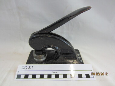
A cast iron seal press, . This was used by Heywood Sewerage Authority to emboss agreements and official documents. Die is still attached to the press. It reads: Heywood Sewerage Authority 1970 Small metal machine painted black . Two dies are attached with the seal of Heywood Sewerage Authority. Paper is placed between the dies, the handle depressed and the seal embossed on the paper under pressure as a blind (inkless) embossing. The seal consists of two circles with the wording "Heywood Sewerage Authority". Cast iron seal embossing press , painted black colour, silver coloured metal die Heywood Sewerage Authority 1970/ HSA written in white texta on front of baseheywood, sewerage, public administration -
 City of Moorabbin Historical Society (Operating the Box Cottage Museum)
Equipment - Omega Breast Reliever, 1920
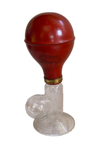
Equipment used by Emma Warburton, a midwife, who lived in the City of Moorabbin. The pump was used by women who needed that extra help to relieve the pressure build-up in their breasts when lactating. The pump was made by J.G. Ingram & Sons Ltd, and sold in the early 1900’s.Owned and used by one of the pioneer families in the City of MoorabbinGlass tube with a collecting reservoir that opens into a funnel (or breast piece). Round red rubber bulb attached to one end of the glass. Stamp in black ink on red bulb reads "Ingram's/'Omega'/London."nursing, midwife, emma warburton, cheltenham, moorabbin, city of moorabbin, mentone, child birth, breast feeding, medical equipment, breast pump -
Bendigo Historical Society Inc.
Document - SOUTH BELLE VUE MINE - FIRE AT THE SOUTH BELLE VUE & TRUE BLUE MINES
Handwritten copy of a report in the Bendigo Advertiser 19th, 20th and 21st August 1894 of an explosion and fire at the South Belle Vue Mine Enginehouse. Water pressure was a problem with their fire fighting efforts. While this was happening a messenger came tosay the Enginehouse at the True Blue Mine was also on fire. Both fires were believed to be deliberately lit. A resident saw a man carrying a lighted torch through the bush.document, gold, south belle vue mine, south belle vue mine, true blue mine, fire at the south belle vue & true blue mines, angus kennedy, mr r woods, golden squarte fire brigade, capt houston, national ins. coy, mr cottie -
 Forests Commission Retired Personnel Association (FCRPA)
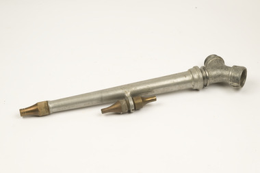
Fire hose nozzle(s) with Y joint and brass attachments
Hose nozzle size can affect the stream of water. A smaller hole puts out a longer stream but with less volume. A longer water stream is useful when trying to extinguish fire or sparks high in the tree tops. They were often used with high pressure pumps like the Pacific Marine.Aluminum fire hose nozzle(s) with Y joint and interchangeable brass attachments For 1.5 inch hose with screw attachments rather than modern twist-camm locks. The main nozzle is aluminum alloy and the interchangeable nozzles are made of brass.bushfire