
Showing 81 items matching "engine specifications"
-
 Moorabbin Air Museum
Manual (item) - Snecma Atar Engine Specifications, Atar
... Snecma Atar Engine Specifications ...Commonwealth Aircraft Corporation Atar Manual Snecma Atar Engine Specifications ...Commonwealth Aircraft Corporation -
Moorabbin Air Museum
Manual (item) - Boeing 502 Gas Turbine Engine Specifications, Model S;pecification Boeing 502-10MA Gas Turbine Engine
... Boeing 502 Gas Turbine Engine Specifications...Model S;pecification Boeing 502-10MA Gas Turbine Engine Manual Boeing 502 Gas Turbine Engine Specifications ... -
Moorabbin Air Museum
Manual - Avon engines, Rolls Royce Engine Performance Specifications and Installation Notes MK 532
... Rolls Royce Engine Performance Specifications and Installation Notes MK 532...Avon engines Various performance graphs Installation notes Performance graphs & installation notes for Avon Mk 532 engine, circa 1960 Rolls Royce Engine Performance Specifications and Installation Notes MK 532 Manual Avon engines ...Performance graphs & installation notes for Avon Mk 532 engine, circa 1960non-fictionPerformance graphs & installation notes for Avon Mk 532 engine, circa 1960various performance graphs, installation notes -
 Wodonga & District Historical Society Inc
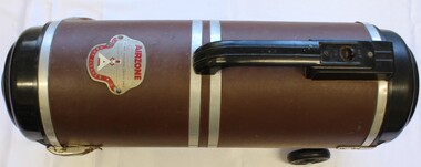
Domestic object - Airzone Vacuum Cleaner, 1950
... Metal logo for Airzone including engine specifications...Domestic appliances Standard Telephones and Cables Pty Ltd Metal logo for Airzone including engine specifications Model 30 Airzone Vacuum Cleaner and accessories. ...Standard Telephones and Cables Pty Ltd was a telecommunications company that began as part of Western Electric, a telephone manufacturing company set up by Alexander Graham Bell. Following the First World War, Western Electric diversified to include electric generators and wireless receivers, all still imported. In 1925, Western Electric was sold to the International Telephone and Telegraph Company. In Australia, it became known as Standard Telephones and Cables (Australasia) They worked closely the Postmaster Generals department to set up telephone and radio networks throughout Australia. Its first factory was in Chippendale, New South Wales but ut developed to have branches in all stated of Australia. By the end of the Second World War STC was Australia's biggest manufacturer due to its critical role in producing telecommunications equipment, domestic radio receivers, telecom cables, military equipment and electron tubes. The company returned to peacetime manufacture. Rather than reduce staff it used its excess capacity to produce electric irons and other domestic appliances including vacuum cleaners and floor polishers. This model was produced at the beginning of the 1950s. It was once owned by Mr. Stiff from Stiff and Gannon, Wodonga.This item has local and national significance. It was used in a local Wodonga business and is representative of domestic appliances used in the 1950s. It also has national significance as it is an excellent example of good produced by the manufacturing industry in Australia during that period.Model 30 Airzone Vacuum Cleaner and accessories. Manufactured in AustraliaMetal logo for Airzone including engine specificationsdomestic appliances, standard telephones and cables pty ltd -
Moorabbin Air Museum
Manual - Avco Lycoming Gas Turbine Engines, Lycoming T53-L-13 Gas Turbine Engine Technical Notes
... engine...Specifications...Avco Lycoming gas turbine engines History of Lycoming Theory of gas turbines Baisc gas turbine engine Specifications Airflow description Major engine assemblies Overview of Lycoming T53-L-13 gas turbine engine for training purposes, circa 1970 Spiral bound manual Lycoming T53-L-13 Gas Turbine Engine Technical Notes Manual Avco Lycoming Gas Turbine Engines ...Overview of Lycoming T53-L-13 gas turbine engine for training purposes, circa 1970Spiral bound manualnon-fictionOverview of Lycoming T53-L-13 gas turbine engine for training purposes, circa 1970history of lycoming, theory of gas turbines, baisc gas turbine engine, specifications, airflow description, major engine assemblies -
Moorabbin Air Museum
Book - Aircraft engines, Aircraft Engine Maintenance
... ...Engine specifications...Aircraft engines Principles & types Construction & detail Tools/equipment & methods Servicing & operation Carburettors & induction systems Fuel systems Lubrication Elementary electricity Ignition Starters & generators Instruments Propellers Periodic check Power plant installation Top overhaul Trouble shooting Fuels & oils Engine specifications Fundamentals of engine construction, operation & maintenance, circa 1939 Aircraft Engine Maintenance Book Aircraft engines ...Fundamentals of engine construction, operation & maintenance, circa 1939non-fictionFundamentals of engine construction, operation & maintenance, circa 1939principles & types, construction & detail, tools/equipment & methods, servicing & operation, carburettors & induction systems, fuel systems, lubrication, elementary electricity, ignition, starters & generators, instruments, propellers, periodic check, power plant installation, top overhaul, trouble shooting, fuels & oils, engine specifications -
Moorabbin Air Museum
Document - Bristol Siddeley Viper Engine Information And Specifications, Viper 11 for Jet Trainer Aircraft
... Bristol Siddeley Viper Engine Information And Specifications...Collection of loose papers, most stapled together Viper 11 for Jet Trainer Aircraft Document Bristol Siddeley Viper Engine Information And Specifications ... -
Moorabbin Air Museum
Manual (Item) - Beechcraft Queen Air Model 65 Parts Catalogue
... Scottish Aviation Prestwick Pioneer Alvis Leonides 502/4 Engine Specifications Book Level of Importance: World. ...Scottish Aviation Prestwick Pioneer Alvis Leonides 502/4 Engine Specifications Book Level of Importance: World. ...Description: 23 pages. Published by Scottish Aviation. Published on unknown date. Scottish Aviation Prestwick Pioneer Alvis Leonides 502/4 Engine Specifications Book Level of Importance: World. -
 National Wool Museum
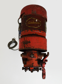
Machine - Shearing Motor, Sunbeam, 1960-69
... On the right-hand side of the engine, a specification plate is located on the central cylinder. ...On the right-hand side of the engine, a specification plate is located on the central cylinder. ...With more and more woolsheds being connected to power lines, the need for electric shearing gear markedly increased from the 1960s onwards. The greater economy made electric gear an attractive proposition to many graziers. Requiring only an electric shearing motor, for small and medium scale operations, electric shearing motors were a more economical way of shearing a wool clip. The other option for graziers was Overhead shearing gear, which also required an Engine to provide shared power to a row of shearing stations. Still working, this Sunbeam Electric Shearing Motor – Heavy Duty Model, features a slow speed motor totally enclosed for protection against dust and insects. The full bearing down tube is easily removed and stored to be out of the way when not in use (not pictured). Providing 0.5 hp, which is twice the power ever needed for shearing sheep, this buffer allows for fluctuations in voltages that can occur in rural districts. Inventor Frederick Wolseley made the world's first commercially successful power-shearing system in Australia in 1888. US company Cooper, which had been founded in 1843 as a maker of sheep dip, began selling Wolseley equipment in the USA in 1895. The Chicago Flexible Shaft Company successfully entered the power-shearing market a few years later and entered into a joint venture with Cooper. It set up a branch in Sydney and sold shearing sets, and engines to power them, into the Australian market. In 1921 the US parent company, realising it needed to make products whose sales were not as seasonal as those of shearing equipment, made its first household appliances and branded them Sunbeam. In 1933, changes in exchange rates and taxes led the company to manufacture engines and shearing equipment in Australia via subsidiary Cooper Engineering, which changed its name to Sunbeam in 1946. Although most Australians know of this company as a major manufacturer of household appliances, its rural division flourished and retained the Sunbeam name for shearing equipment even after it was taken over by New Zealand company Tru-Test in 2001. This 0.5 horsepower vertical brushed motor air-cooled engine was designed to drive a single shearing plant. From the central cylinder which features a yellow “Sunbeam” sticker, a grey 240v power lead can be found on the left-hand side. A blue capacitor is located next to this power lead. Below, two legs extend and meet to form a foot which is fastened to a wall. On the right-hand side of the engine, a specification plate is located on the central cylinder. A yellow directional arrow sticker is located on the rotating section of the engine below the specification plate (location for photography, this section is designed to rotate and hence this sticker is not fixed in this location). At the rear of the cylinder, a plastic cap with small air cut outs protects the air-cooled engine from contaminants. At the front of the engine, the location for securing the bearing down tube is located. On the right-hand side of the lock for the bearing down tube is the handle, to which a string is often attached for switching the motor on and off by a shearer bent at the waist (not pictured). Sticker. Gold writing. Front of shearing motor “Sunbeam” Plate. Inscribed. Side of shearing motor. “Sunbeam / SHEARING MOTOR / MADE IN AUSTRALIA / 0.5 H.P. / 220/240 V / 1 PHASE A.C. / 4.0 AMPS / 50 C/S. / CONT. RTG. / 1425 R.P.M. / CLASS A INSUL / NO. J244560 / TYPE: NSB5C2/49." sheep sheering, shearing equipment, sunbeam, electric shearing motor -
 Trafalgar Holden Museum
Vehicle - Holden model FB sedan, 1960 - 1961
... The engine bore was still 3 inches (76 mm), the last model with that specification. ...The engine bore was still 3 inches (76 mm), the last model with that specification. ...The FB was promoted as being longer, lower, more spacious and more powerful than the FC model, but in reality it was only slightly so on each count overerall length was 5.5 inches (140 mm) greater, although the wheelbase remained the same. The engine bore was still 3 inches (76 mm), the last model with that specification. Engine capacity was 138 cubic inches (2.16 L) but the compression ratio was raised. However, the resulting extra 4 brake horsepower (3 kW) of power did not compensate for the greater weight of the FB, so performance was inferior to that of its predecessor. Changes were also made to the brakes, front coil springs, air cleaner and clutch. Obvious styling differences were the lower bonnet, finned rear mudguards with new taillights (on the sedans and wagons only) and a wrap-around windscreen. Seating was improved, as was the instrument panel. A refinement of the FC model but appearance significantly changed with a wraparound windscreen, lower bonnet and finned rear guards.. This vehicle was purchased in NSW The interior was in excellent condition bur required extensive exterior work to bring it back to its original condition, It had a mileage of 8500. A refinement of the FC model but appearance significantly changed with a wraparound windscreen, lower bonnet and finned rear guards. It was the first Holden with acrylic paintwork.Two tone grey body , four door FB Holden sedan. Finned rear mudguard,. Holden Special Registered number 63452-Hholden, automobile, 1960, car -
 Flagstaff Hill Maritime Museum and Village
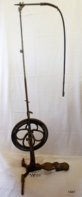
Equipment - Dentist Drill, Late 19th century
... White Catalogue of Dentist Instruments listed a 12 ½ inch wheel diameter dental engine, with 14 bright steel parts, for sale at US $55 In today’s market, this is the equivalent to US $1200 approx. The specifications...White Catalogue of Dentist Instruments listed a 12 ½ inch wheel diameter dental engine, with 14 bright steel parts, for sale at US $55 In today’s market, this is the equivalent to US $1200 approx. The specifications ...The design of this and other similar treadle powered dental engine (or dentist drill) was in common use by dentists from the 1870’s into the 1920's. When electricity became accessible to most communities the electrically powered dental engines began to take over from the treadle power. Over the ages teeth were extracted using picks and scissors and other gouging instruments. Bow drills, hand drills and even a "bur thimble" drill were later used to prepare cavities for filling. Some drills were made bendable by attaching flexible shanks between the metal bur and the handle, giving access to the teeth at the back of the mouth. Other mechanical devices were introduced along the way, such as clockwork drills, but they were hard to handle and inefficient. Over the centuries “dentistry has been performed by priests, monks and other healers. This was followed by barbers; the barber’s chair may well have been the precursor to the dental chair. “(SA Medical Heritage Society Inc.) In 1871 James Morrison patented the first commercially manufactured 'foot treadle dental engine', the first practica dental engine although others had been introduced as early as 1790 (by John Greenwood). Handmade steel burs or drills were introduced for dental handpieces, taking advantage of the significant increase in the speed of the drill. In 1891 the first machine-made steel burs were in use. The treadle drill reduced the time to prepare a cavity from hours to less than ten minutes. In 1876 the Samuel S. White Catalogue of Dentist Instruments listed a 12 ½ inch wheel diameter dental engine, with 14 bright steel parts, for sale at US $55 In today’s market, this is the equivalent to US $1200 approx. The specifications of that dental engine are very similar to the this one in our Flagstaff Hill Maritime Village’s collection. It is interesting to note that workings of a similar treadle dentist drill were used and modified to power a treadle spinning wheel of one of the volunteer spinners at Flagstaff Hill Maritime Village. The foot treadle dental engine was a milestone in dental history. “Historic importance of treadle powered machines; they made use of human power in an optimal way” (Lowtech Magazine “Short history of early pedal powered machines”) The invention of a machine to speed up the process of excavation of a tooth lead to the invention of new burs and drills for the handpieces, improving speed and the surgical process of dentistry. They were the fore-runner of today’s electrically powered dental engines. This treadle-powered dentist drill, or dentist engine, is made of iron and steel and provides power for a mechanical dental hand-piece that would be fitted with a dental tool. The drill has a three footed cast iron base, one foot being longer than the other two. A vertical C shaped frame is joined into the centre of the base, holding an axle that has a driving-wheel (or flywheel) and connecting to a crank. A slender, shoulder height post, made from telescoping pipes, joins into the top of this frame and is height adjusted by a hand tightened screw with a round knob. On the post just above the frame is a short metal, horizontal bar (to hold the hand-piece when it is not in use). A narrow tubular arm is attached to the top of the stand at a right angle and can move up and down. At the end of the arm is a firmly fixed, flexible rubber hose protected for a short distance by a sheath of thin metal. At the end of the hose there is a fitting where the drill’s hand-piece would be attached; a small, silver coloured alligator clip is also at the end. A treadle, or foot pedal, is hinged to the heel to the long foot of the base, and joined at the toe to the crank that turns the driving-wheel. There is a spring under the toe of the treadle. The metal driving-wheel has a wide rim. Touching the inside of the rim are four tubular rings that bulge towards the outside of the driving-wheel, away from the pole, and all meet at the hub of the axle. The axle is bulbous between the inside of the driving-wheel and the frame then passes through the frame and is attached on the other side. The driving-wheel has a groove around which a belt would sit. The belt would also fit around a pulley on the arm, at the top of the post. The pulley is joined to a rod inside the arm and this spins the drill's hand-piece and dental tool holder. The two shorter feet of the base are made from a long metal bar that has been curved outwards, and its centre is bolted to the base of the pole. Under the ends of the curved legs of the base are wedge shaped feet. The driving-wheel is decorated in light coloured paint on both sides, each side having three sets of floral decals evenly spaced around them, and each about a sixth of the wheel's circumference. Similar decoration is along the sides of the frame. The foot pedal has decorative cutout patterns in the centre of the foot and at the toe. On the long foot of the stand is some lettering with a fine, light coloured border around it. The lettering is hard to read, being a dark colour and flaking off. There are also remnants of fine, light coloured flourishes. The foot pedal has lettering of the maker’s trade mark cast into the metal at the ball of the foot. Lettering on the base is peeling and difficult to read. The foot pedal has a trade mark cast into it that looks like a combination of ‘C’ , ‘S’ , ‘A’, ‘R’. flagstaff hill, warrnambool, shipwrecked coast, flagstaff hill maritime museum, maritime museum, shipwreck coast, flagstaff hill maritime village, great ocean road, dentist, teeth, dental drill, dental engine, treadle drill, foot powered drill, treadle engine, orthodontics, dental surgery, james morrison -
 Flagstaff Hill Maritime Museum and Village
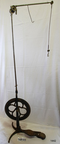
Equipment - Dentist Drill, Late 19th century
... White Catalogue of Dentist Instruments listed a 12 ½ inch wheel diameter dental engine, with 14 bright steel parts, for sale at US $55 In today’s market, this is the equivalent to US $1200 approx. The specifications...White Catalogue of Dentist Instruments listed a 12 ½ inch wheel diameter dental engine, with 14 bright steel parts, for sale at US $55 In today’s market, this is the equivalent to US $1200 approx. The specifications ...The design of this and other similar treadle powered dental engine (or dentist drill) was in common use by dentists from the 1870’s into the 1920's. When electricity became accessible to most communities the electrically powered dental engines began to take over from the treadle power. Over the ages teeth were extracted using picks and scissors and other gouging instruments. Bow drills, hand drills and even a "bur thimble" drill were later used to prepare cavities for filling. Some drills were made bendable by attaching flexible shanks between the metal bur and the handle, giving access to the teeth at the back of the mouth. Other mechanical devices were introduced along the way, such as clockwork drills, but they were hard to handle and inefficient. Over the centuries “dentistry has been performed by priests, monks and other healers. This was followed by barbers; the barber’s chair may well have been the precursor to the dental chair. “(SA Medical Heritage Society Inc.) In 1871 James Morrison patented the first commercially manufactured 'foot treadle dental engine', the first practica dental engine although others had been introduced as early as 1790 (by John Greenwood). Handmade steel burs or drills were introduced for dental handpieces, taking advantage of the significant increase in the speed of the drill. In 1891 the first machine-made steel burs were in use. The treadle drill reduced the time to prepare a cavity from hours to less than ten minutes. In 1876 the Samuel S. White Catalogue of Dentist Instruments listed a 12 ½ inch wheel diameter dental engine, with 14 bright steel parts, for sale at US $55 In today’s market, this is the equivalent to US $1200 approx. The specifications of that dental engine are very similar to the this one in our Flagstaff Hill Maritime Village’s collection. It is interesting to note that workings of a similar treadle dentist drill were used and modified to power a treadle spinning wheel of one of the volunteer spinners at Flagstaff Hill Maritime Village. The foot treadle dental engine was a milestone in dental history. “Historic importance of treadle powered machines; they made use of human power in an optimal way” (Lowtech Magazine “Short history of early pedal powered machines”) The invention of a machine to speed up the process of excavation of a tooth lead to the invention of new burs and drills for the handpieces, improving speed and the surgical process of dentistry. They were the fore-runner of today’s electrically powered dental engines. This treadle-powered dentist drill, or dentist engine, is made of iron and steel and provides power for a mechanical dental handpiece that would be fitted with a dental tool. On the foot is painted lettering naming it "The Brentfield" and there is a fine line of light coloured paint creating a border around the name. The paint under the lettering is peeling off. The drill has a Y-shaped, three footed cast iron base, one foot being longer than the other two. A vertical frame is joined into the centre of the base, holding an axle that has a driving-wheel (or flywheel) and connecting to a crank. A slender, shoulder height post, made from adjustable telescoping pipes, joins into the top of this frame. On the post just above the frame is a short metal, horizontal bar (to hold the hand-piece when it is not in use). A narrow tubular arm is attached to the top of the stand at a right angle and can move up, down and around. There is a pulley each side of the joint of the arm and a short way along the arm is fitted a short metal pipe. A little further along the arm a frayed-ended cord hangs down from a hole. At the end of the arm is another pulley and a joint from which hangs a long, thin metal pipe with two pulleys and a fitting on the end. A treadle, or foot pedal, is joined to the long foot of the base, and joined at the toe to the crank that turns the driving-wheel. The metal driving-wheel has a wide rim. Touching the inside of the rim are four tubular rings that bulge towards the outside of the driving-wheel, away from the pole, and all meet at the hub of the axle. The axle fits between the inside of the driving-wheel and the frame then passes through the frame and is attached on the other side. The driving-wheel has a groove around which a belt would sit. The belt would also fit around a pulley on the arm, at the top of the post. The pulley is joined to a rod inside the arm and this spins the drill's hand-piece and dental tool holder. The foot pedal has a cross-hatch pattern on the heel and the ball of the foot has tread lines across it. The end of the toe and the instep areas have cut-out pattern in them. "The ____/ Brentfield / __ DE IN L___" (Made in London) painted on the long foot of the base. Marked on the drill connection is “Richter De Trey, Germany”flagstaff hill, warrnambool, shipwrecked coast, flagstaff hill maritime museum, maritime museum, shipwreck coast, flagstaff hill maritime village, great ocean road, dentist, teeth, dental drill, dental engine, treadle drill, foot powered drill, treadle engine, orthodontics, dental surgery, james morrison, the brentfield, richter de trey, german dental fitting, london dental drill -
Federation University Historical Collection
Letter, Specifications for taking down , carting and re-erecting engine gear puddlers
... Taking down of equipment of the Berry Consols Gold Mining Company No.1 Mine. engine gear air pipes surface horizontal gear machine horses sluice deck tram roads step ladders engine house balance weights sludge vat Handwritten specifications. Specifications for taking down , carting and re-erecting engine gear puddlers Letter ...Taking down of equipment of the Berry Consols Gold Mining Company No.1 Mine. Handwritten specifications.engine, gear, air pipes, surface horizontal gear, machine horses, sluice deck, tram roads, step ladders, engine house, balance weights, sludge vat -
Federation University Historical Collection
Document - Document - Design, E J Barker: University of Melbourne: Bachelor of Mechanical Engineering; Engineering Design Part II, 1946
... The Library building at Mount Helen Campus is named after him. e j barker jack barker melbourne university engineering diploma of mechanical engineering diploma of electrical engineering school of mines ballarat smb diploma in education vice principal principal foundation director ballarat college of advanced education bcae bachelor of mechanical engineering library mount helen campus engineering drawing design specifications manufacture extruder addition hydraulic press flywheel cams valve gear inlet valve exhaust valve 6 cylinder truck engine autoclave brown coal Four manila folders with design assessment in each. ...Four folders containing an Engineering Design Part II Project. Each has detailed written information and drawings. No.1: To design an Extruder Addition to the hydraulic press in the plate shop to enable it to be used as an extruding press to operate on materials similar in behaviour to a wax. No. 2: To design a flywheel of uniform strength of not less than 25 feet. No 3: To design cams, valve gear and inlet and exhaust valves for a 6 cylinder truck engine. No 4: To design an experimental brown coal autoclave for drying brown coal in 10 kilogram lots. Jack chose to do Engineering while still at Footscray Technical School as it gave access to Diploma Courses and tertiary studies. This enabled him to enter the University of Melbourne and do a Bachelor in Mechanical Engineering - 1945, 1946, and 1947. In 1948 he did a Diploma in Education at Melbourne University. From this path he was able to follow a career in teaching and his first appointment was at the School of Mines in Ballarat, (SMB) 1949. He became the first Vice Principal of SMB in 1960 and then Principal in 1964 to 1976. From 1976 to his retirement in 1987, he was the Foundation Director of Ballarat College of Advanced Education (BCAE). The Library building at Mount Helen Campus is named after him.Four manila folders with design assessment in each. Each folder has written descriptions and detailed drawings.e j barker, jack barker, melbourne university, engineering, diploma of mechanical engineering, diploma of electrical engineering, school of mines ballarat, smb, diploma in education, vice principal, principal, foundation director, ballarat college of advanced education, bcae, bachelor of mechanical engineering, library, mount helen campus, engineering drawing, design, specifications, manufacture, extruder addition, hydraulic press, flywheel, cams, valve gear, inlet valve, exhaust valve, 6 cylinder truck engine, autoclave, brown coal -
Federation University Historical Collection
Document - Document - Design, E J Barker: University of Melbourne: Bachelor of Mechanical Engineering; Machine Design Assignments, 1947
... The Library building at Mount Helen Campus is named after him. e j barker jack barker melbourne university engineering diploma of mechanical engineering diploma of electrical engineering school of mines ballarat smb diploma in education vice principal principal foundation director ballarat college of advanced education bcae bachelor of mechanical engineering library mount helen campus engineering drawing design specifications manufacture bristo plastic industries australian iron and steel olympic cable factory centre lathe head stock multitubular double effect evaporator 120 hp diesel engine Manila folders with design assessments. ...Four folders of Machine Design projects. No.1: a. Reports on visits to various industries: Bristo Plastic Industries. b. Australian Iron and Steel. c. Olympic Cable Factory No 2: Medium Duty Centre Lathe Head Stock No.3: Vertical Multitubular Double Effect Evaporator No.4: Design and Drawings of 120 HP Diesel Engine Jack chose to do Engineering while still at Footscray Technical School as it gave access to Diploma Courses and tertiary studies. This enabled him to enter the University of Melbourne and do a Bachelor in Mechanical Engineering - 1945, 1946, and 1947. In 1948 he did a Diploma in Education at Melbourne University. From this path he was able to follow a career in teaching and his first appointment was at the School of Mines in Ballarat, (SMB) 1949. He became the first Vice Principal of SMB in 1960 and then Principal in 1964 to 1976. From 1976 to his retirement in 1987, he was the Foundation Director of Ballarat College of Advanced Education (BCAE). The Library building at Mount Helen Campus is named after him.Manila folders with design assessments. Written descriptions and detailed drawings.e j barker, jack barker, melbourne university, engineering, diploma of mechanical engineering, diploma of electrical engineering, school of mines ballarat, smb, diploma in education, vice principal, principal, foundation director, ballarat college of advanced education, bcae, bachelor of mechanical engineering, library, mount helen campus, engineering drawing, design, specifications, manufacture, bristo plastic industries, australian iron and steel, olympic cable factory, centre lathe head stock, multitubular double effect evaporator, 120 hp diesel engine -
Federation University Historical Collection
Document - Document - Design, E J Barker: University of Melbourne: Bachelor of Mechanical Engineering; Class notes and definitions
... The Library building at Mount Helen Campus is named after him. e j barker jack barker melbourne university engineering diploma of mechanical engineering diploma of electrical engineering school of mines ballarat smb diploma in education vice principal principal foundation director ballarat college of advanced education bcae bachelor of mechanical engineering library mount helen campus engineering drawing design specifications manufacture heat engines internal combustion engine symbols of physical quantities hisory people inventions instructors examiners report refrigeration Handwritten and typed notes. ...Notes are definitions and information on various aspects of Mechanical Engineering - Heat Engines, Internal Combustion Engines, Symbols for Physical Quantities, Historical-people and their inventions, Minutes of Meeting of Instructors and Examiners, Engineering Thermodynamics III, Refrigeration. Jack chose to do Engineering while still at Footscray Technical School as it gave access to Diploma Courses and tertiary studies. This enabled him to enter the University of Melbourne and do a Bachelor in Mechanical Engineering - 1945, 1946, and 1947. In 1948 he did a Diploma in Education at Melbourne University. From this path he was able to follow a career in teaching and his first appointment was at the School of Mines in Ballarat, (SMB) 1949. He became the first Vice Principal of SMB in 1960 and then Principal in 1964 to 1976. From 1976 to his retirement in 1987, he was the Foundation Director of Ballarat College of Advanced Education (BCAE). The Library building at Mount Helen Campus is named after him.Handwritten and typed notes. Plain and lined sheets.e j barker, jack barker, melbourne university, engineering, diploma of mechanical engineering, diploma of electrical engineering, school of mines ballarat, smb, diploma in education, vice principal, principal, foundation director, ballarat college of advanced education, bcae, bachelor of mechanical engineering, library, mount helen campus, engineering drawing, design, specifications, manufacture, heat engines, internal combustion engine, symbols of physical quantities, hisory, people, inventions, instructors, examiners, report, refrigeration -
 Federation University Historical Collection
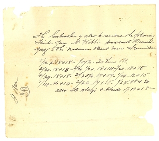
Document, Contract for the Madame Bent Gold Mining Company, 1886, 1886
... ] from Mr Webb's paddock ... to the Madame Bent Mine Grenville ... .2) Specification for the taking doan, removal and reerection 2 Engines 2 boilers pumping gear, Bob, Poppett heads and Capstone etc, for teh Mdame Bent G.M.Cy Grenville. ...] from Mr Webb's paddock ... to the Madame Bent Mine Grenville ... .2) Specification for the taking doan, removal and reerection 2 Engines 2 boilers pumping gear, Bob, Poppett heads and Capstone etc, for teh Mdame Bent G.M.Cy Grenville. ...Handwritten on foolscap paper, with red seal on last page.1) The Subcontractor is also to remove the following [ ? ] from Mr Webb's paddock ... to the Madame Bent Mine Grenville ... .2) Specification for the taking doan, removal and reerection 2 Engines 2 boilers pumping gear, Bob, Poppett heads and Capstone etc, for teh Mdame Bent G.M.Cy Grenville. The company will provide ... .3) Morey's Coys yard, together with holding down bolts, and the following ... .4) to the extent of Bed ... Carpentry Work - To carefully take down the poppet heads and co... and erect the same on the claim complete ... .5) Engine Framing as shown for the winding engines and pumping engines. Properly fitted to get ... .6) The boilers to be fed in front. The contractor to cut and drill all necessary holes in the boilers and pipes - to fire blow ... The contractor to make good any damage or breakage or loss to machinery or any part hereof that may occur to it during the removal of the reerection of same. The loss or damage, if any, not being made good by the contractor, or in the event of the works not being proceeded with to the satisfaction of the Company;s Engineer, The company's Engineer hereby ... .7) of the whole of the works, and in default thereof the COntractor shall forfeit the sum of two pounds ... Signed James Malcolm Witness L. Menz The Common seal of the company was affixed this thirteenth day of December:/86 by its manager James Burrell in the presence of [illegible] managers Seal - Madame Bent Gold Mining Company Durham Lead Buninyongmadame bent gold mining company, richard squire, james malcolm, james burrell -
 Mission to Seafarers Victoria
Model - Model Ship, H.M.S Dreadnought, 2014
... Original specifications: Length 526 ft; beam 82 ft; speed: 21 knots cruising Crew complement: 657; Armament: 10 12inch guns; 18 12 pdr guns( 4 shown on model) ; Engines: two turbines driving 4 shafts; weight: 17,900 tons fully laden; coal capacity 2977 tons; The ship was broken up for scrap in 1920 - David Lumsden donor and modelmaker ...Original specifications: Length 526 ft; beam 82 ft; speed: 21 knots cruising Crew complement: 657; Armament: 10 12inch guns; 18 12 pdr guns( 4 shown on model) ; Engines: two turbines driving 4 shafts; weight: 17,900 tons fully laden; coal capacity 2977 tons; The ship was broken up for scrap in 1920 - David Lumsden donor and modelmaker Detailed Model of the Dreadnought model ships h.m.s. dreadnought battleships ww1 david lumsden two card labels adhered to plinth: "David Lumsden 2014 Scale 1:72" "H M S Dreadnought" 90% cardboard model of early 20th C. battleship one white ensign; on a polished wood plinth with cardboard hand lettered labels. ...A modern detailed replica to scale 1:200 of the early 20th C battleship launched in 1906. " The dreadnought class defined the basic form of battleships up to the 2nd WW. Original specifications: Length 526 ft; beam 82 ft; speed: 21 knots cruising Crew complement: 657; Armament: 10 12inch guns; 18 12 pdr guns( 4 shown on model) ; Engines: two turbines driving 4 shafts; weight: 17,900 tons fully laden; coal capacity 2977 tons; The ship was broken up for scrap in 1920 - David Lumsden donor and modelmaker Detailed Model of the Dreadnought 90% cardboard model of early 20th C. battleship one white ensign; on a polished wood plinth with cardboard hand lettered labels. Decks painted pale gunship grey and below waterline bright red. Model on polished wood plinth with bevelled edge.two card labels adhered to plinth: "David Lumsden 2014 Scale 1:72" "H M S Dreadnought"model ships, h.m.s. dreadnought, battleships, ww1, david lumsden -
 B-24 Liberator Memorial Restoration Australia Inc
Pratt & Whitney R 1830 Radial Engine (Informational Entry)
... Between Pratt & Whitney and numerous licensed companies, there were over 180,000 of these engines manufactured in a number of specifications. The B-24 Liberator would have been their major recipient but other famous aircraft using the same engine were the Consolidated Catalina flying boat and the Douglas DC3/C47/Dakota. ...Between Pratt & Whitney and numerous licensed companies, there were over 180,000 of these engines manufactured in a number of specifications. The B-24 Liberator would have been their major recipient but other famous aircraft using the same engine were the Consolidated Catalina flying boat and the Douglas DC3/C47/Dakota. ...Between Pratt & Whitney and numerous licensed companies, there were over 180,000 of these engines manufactured in a number of specifications. The B-24 Liberator would have been their major recipient but other famous aircraft using the same engine were the Consolidated Catalina flying boat and the Douglas DC3/C47/Dakota. Refer Wikipedia link for other aircraft that used this engine.As a result of the significant and ongoing usage of these engines in civil aircraft such as the Douglas DC3, they are by no means rare. Many parts can still be sourced new and there are several companies that have the capacity to rebuild these engines to an airworthy standard.The Pratt & Whitney R 1830 is a double row 14 cylinder air cooled radial engine with a capacity of 1830 cubic inches (30 litres), developing some 1200 horsepower at a maximum 2700 rpm.radial engine, twin wasp, r1830 -
 B-24 Liberator Memorial Restoration Australia Inc
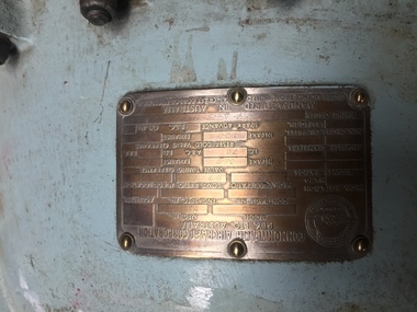
Pratt & Whitney R 1830 Radial Engine, 54828 (CAC)
... This engine was a Commonwealth Aircraft Corporation (CAC) build, and had been upgraded to 92 specification at some time. ...This engine was a Commonwealth Aircraft Corporation (CAC) build, and had been upgraded to 92 specification at some time. ...This engine was a Commonwealth Aircraft Corporation (CAC) build, and had been upgraded to 92 specification at some time. This engine as acquired, was completely seized and great difficulty was encountered in dismantling it. The pistons in Nos 1, 13, 3, 2 and 5 had "grown" into the cylinder bores requiring some unorthodox methods to remove them. The cylinder barrels have been brought up to a reasonable standard, those beyond repair were replaced from stock. After getting various parts from the US, this engine was eventually brought up to running order.The Pratt & Whitney R 1830 is a double row 14 cylinder air cooled radial engine with a capacity of 1830 cubic inches, (30 litres), developing some 1200 horsepower at a maximum 2700 rpm.Engine Number 54828 -
 Bendigo Historical Society Inc.
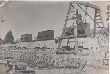
Photograph - Napoleon Reef Gold Mine Battery Site, 1936
... The design of engine room, change house and machine shops is now in hand and erection will proceed as soon as working plans and specifications are prepared.' ...The design of engine room, change house and machine shops is now in hand and erection will proceed as soon as working plans and specifications are prepared.' ...The Napoleon (BML) gold mine (1932) was located near McDougall Road, Golden Gully, between Martin and Hattam Street. It had a depth of 921 feet. It was one of the latest and most lavish of Bendigo's mines. Plant and equipment were electrically driven. The four-compartment shaft, extra large by goldfield's standards, measured 17 feet 6 inches by 5 feet 2 inches and was cement lined below 900 feet instead of being red gum boxed as was the usual practice. The workshop was equipped to carry out all repairs for the equally lavish BML mines on the Nell Gwynne and Carshalton reefs. (The Gold Mines of Bendigo, Book 2, Arthur Victor Palmer) 'Napoleon BML Mines No Liability have issued a report for the fortnight ended September 5, where it states that the development scheme has been formulated and necessary equipment is being ordered. The Napoleon main shaft, (about 1700 feet south of the old Napoleon shaft) will be a four compartment shaft (17ft 6 inches by ft 2 inches inside the timber). aLevels will be opened at approximately 100 ft vertical intervals and cross-cuts extended approximately 125 ft each side of centre country to explore a cross-section across the anticline opposite to the shaft. At every fifth level, main drives will be extended north to connect with the old Napoleon shaft and south approximately 1800 ft. At the latter point, another cross-section of the anticline will be explored by rising and cross-cutting. The old Napoleon will be unwatered and on the 500ft and 1000 ft levels main drives will be driven to connect with main levels from the Napoleon main shaft to the south as well as being driven north 1800 ft where another cross-section of the anticline will be explored. Cross-sections further north and south may be developed as desired and also at intermediate points if necessary. Clearing and grading of the main shaft site are now in progress and the erection of the office and store building is proceeding. The design of engine room, change house and machine shops is now in hand and erection will proceed as soon as working plans and specifications are prepared.' The main shaft has been commenced at 3ft and advanced 10 ft. to 13 ft. https://trove.nla.gov.au/newspaper/article/10975478?searchTerm=napoleon%20bml (The Argus, 8th. September 1934, 'Mining' page 18) Significant to mining history of Bendigo.Black and white photograph of a stamper head being lowered into position on the battery site of the Napoleon Reef Gold Mine. A wooden gantry supports the battery head as it being lowered. Three large concrete foundations are visible in immediate background, two of which have stampers already in position, the third stamper is being lowered onto the final foundation. In immediate foreground, 'boxing' is erected for future concrete pours. napoleon gold mine, napoleon reef gold mine -
 Monbulk RSL Sub Branch
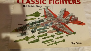
Book, Chartwell Books, Classic fighters : the inside story, 2005
... Each drawing examines what's 'under the skin', clearly showing 'the inside story' - airframe structure, cockpit components, engines, fuel tanks, avionics, machine guns and cannon, missiles and bombs - revealing how the fighters were built, and the weapons they have carried into combat. Each significant component is given a number and is identified in an accompanying key. Moreover, together with stunning photographs, as well as detailed specifications ...'Packed with fascinating facts, this volume contains incredibly detailed cutaway drawings of arguably the greatest fighter aircraft ever flown. Each drawing examines what's 'under the skin', clearly showing 'the inside story' - airframe structure, cockpit components, engines, fuel tanks, avionics, machine guns and cannon, missiles and bombs - revealing how the fighters were built, and the weapons they have carried into combat. Each significant component is given a number and is identified in an accompanying key. Moreover, together with stunning photographs, as well as detailed specifications, the absorbing in-depth development histories provide avid aviation enthusiasts all the information they could wish for about the most exciting warplanes spanning almost a hundred years. The aircraft themselves vary tremendously, from simple, wooden-framed, fabric-covered machines with open cockpits, often firing machine guns through whirring, propellers, to super-fast, highly maneuverable, sophisticated and stealthy fighters armed to the teeth with multi-barrel cannons and missiles that can destroy enemy aircraft from beyond visual range. In between are featured a host of combat-proven fighters, many of which have recorded a plethora of 'firsts' - first jet warplane, first supersonic fighter to enter service, first Mach 2 and even Mach 3 interceptors, first tail-less delta machine, first sweeping-wing machine, first missile-armed fighter, and many more. It is certainly an extraordinarily wide-ranging subject presented in such a fantastically individual manner that it is difficult to imagine a more striking volume in aviation publishing.Ill, p,253.non-fiction'Packed with fascinating facts, this volume contains incredibly detailed cutaway drawings of arguably the greatest fighter aircraft ever flown. Each drawing examines what's 'under the skin', clearly showing 'the inside story' - airframe structure, cockpit components, engines, fuel tanks, avionics, machine guns and cannon, missiles and bombs - revealing how the fighters were built, and the weapons they have carried into combat. Each significant component is given a number and is identified in an accompanying key. Moreover, together with stunning photographs, as well as detailed specifications, the absorbing in-depth development histories provide avid aviation enthusiasts all the information they could wish for about the most exciting warplanes spanning almost a hundred years. The aircraft themselves vary tremendously, from simple, wooden-framed, fabric-covered machines with open cockpits, often firing machine guns through whirring, propellers, to super-fast, highly maneuverable, sophisticated and stealthy fighters armed to the teeth with multi-barrel cannons and missiles that can destroy enemy aircraft from beyond visual range. In between are featured a host of combat-proven fighters, many of which have recorded a plethora of 'firsts' - first jet warplane, first supersonic fighter to enter service, first Mach 2 and even Mach 3 interceptors, first tail-less delta machine, first sweeping-wing machine, first missile-armed fighter, and many more. It is certainly an extraordinarily wide-ranging subject presented in such a fantastically individual manner that it is difficult to imagine a more striking volume in aviation publishing.fighter planes - history, fighter planes -
 Bendigo Historical Society Inc.
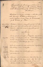
Document - MARKS COLLECTION: HERCULES AND ENERGETIC GOLDMINING CO. SPECIFICATIONS
... Areas in specifications include: repairs to engine and boiler set-up & c., safety valve, whistle, cylinder, stop valve, piston, eccentric, crank shaft, feed pump & eccentric, flywheel very extensive descriptions of all areas, some with diagrams. ...Areas in specifications include: repairs to engine and boiler set-up & c., safety valve, whistle, cylinder, stop valve, piston, eccentric, crank shaft, feed pump & eccentric, flywheel very extensive descriptions of all areas, some with diagrams. ...Handwritten document (15 pages) with two page blue document appended at back. On front of handwritten document : specifications for machinery and ironwork engineer and ironfounder for building plant for the Hercules & Energetic Goldmining Comp., Sandhurst. The contractor is to supply and deliver on the claim of the above Company the following machinery &c - and to get proper receipts for same from the Contractor for the erection of plant. Areas in specifications include: repairs to engine and boiler set-up & c., safety valve, whistle, cylinder, stop valve, piston, eccentric, crank shaft, feed pump & eccentric, flywheel very extensive descriptions of all areas, some with diagrams. Appended to back of document Ironfounders general conditions of contract work required in the making and delivery on the claim machinery &c for a winding plant for the Hercules & |Energetic Co., Drawings prepared by Wm Middleton, Engineer, Sandhurst. Agreement entered into this twelfth day of October, 1878, by and between Messrs Mitchell & Osborne and Hercules and Energetic GMC. Signed by Mitchell & Osborne, per ? Dobson., Wm Middleton ?.bendigo, mining, hercules & energetic mine -
 Bendigo Historical Society Inc.
Document - MARKS COLLECTION: HERCULES AND ENERGETIC COMPANY CONTRACT
... Handwritten document is specifications for carpenters work and erection &c of steam engine, boiling fittings and machinery for the Hercules & Energetic Goldmining Company Sandhurst. ...Handwritten document is specifications for carpenters work and erection &c of steam engine, boiling fittings and machinery for the Hercules & Energetic Goldmining Company Sandhurst. ...Blue A3 document (2 pages) with handwritten specifications attached (15 pages) On front, General Conditions of Contract for 'erection of a steam engine and winding gear for The Hercules & Energetic Co. Prepared by Wm Middleton, Engineer, Sandhurst. Handwritten document is specifications for carpenters work and erection &c of steam engine, boiling fittings and machinery for the Hercules & Energetic Goldmining Company Sandhurst. Specifications include details for boiler setup, engine bed, winding gear bed, soleplates, steam pipes, water elevator and piping, winding gear buildings, windows, rope rollers, flooring poppet heads.bendigo, mining, hercules & energetic mine -
 Bendigo Historical Society Inc.
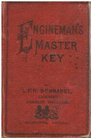
Document - BADHAM COLLECTION: ENGINEMAN’S MASTER'S KEY - BOOK BY L.F.R. SCHNABEL
... Pans and specifications executed for Steam engines. Boilers and Power Plants, hard covered book worn....Plans and specifications executed for Steam engines Boilers and Power Plants. ...Engineman’s Master's Key by L.F.R. Schnabel Licensed Inspector Melbourne, Victoria. Printed at the L.F.R Schnabel Engineering Institute, 443 Bourke St, Melbourne C 1903. Pans and specifications executed for Steam engines. Boilers and Power Plants, hard covered book worn.document, memo, railway, engineman’s master's key - book by l.f.r. schnabel - licensed inspector melbourne victoria, printed at the l.f.r schnabel engineering institute , 443 bourke st melbourne. plans and specifications executed for steam engines, boilers and power plants. -
Port Melbourne Historical & Preservation Society
Booklet, Aircraft and Aero-Engines of Commonwealth Aircraft Corporation 1936 - 1977, 1936 - 1977
... Small oblong book with specifications & pictures of all aircraft and areo-engines produced by the Commonwealth Aircraft Corporation from 1936 - 1977....Built Environment - Industrial Transport - Aviation and Aerodrome Commonwealth Aircraft Corporation Small oblong book with specifications & pictures of all aircraft and areo-engines produced by the Commonwealth Aircraft Corporation from 1936 - 1977. ...Small oblong book with specifications & pictures of all aircraft and areo-engines produced by the Commonwealth Aircraft Corporation from 1936 - 1977.built environment - industrial, transport - aviation and aerodrome, commonwealth aircraft corporation -
Moorabbin Air Museum
Manual (Item) - Pratt & Whitney Commercial Production Engine Data, Pratt & Whitney Aircraft Commercial Production Engines: Specifications and Specification Curves
... Dark blue lever-arch folder Pratt & Whitney Aircraft Commercial Production Engines: Specifications and Specification Curves Manual Pratt & Whitney Commercial Production Engine Data ... -
Moorabbin Air Museum
Document (Item) - TAA DC9 Program Specifications , Fuel & Engines , Flight , Radio Aids , Auto Pilot
... TAA DC9 Program Specifications , Fuel & Engines , Flight , Radio Aids , Auto Pilot Document TAA DC9 Program Specifications , Fuel & Engines , Flight , Radio Aids , Auto Pilot ... -
Moorabbin Air Museum
Document (Item) - TAA DC9 Program Specifications , Fuel & Engines , Flight , Radio Aids , Auto Pilot Copy 2
... TAA DC9 Program Specifications , Fuel & Engines , Flight , Radio Aids , Auto Pilot Copy 2 Document TAA DC9 Program Specifications , Fuel & Engines , Flight , Radio Aids , Auto Pilot Copy 2 ... -
Moorabbin Air Museum
Document (Item) - TAA DC9 Program Specifications , Fuel & Engines , Flight Radio Aids , Auto Pilot Copy 3
... TAA DC9 Program Specifications , Fuel & Engines , Flight Radio Aids , Auto Pilot Copy 3 Document TAA DC9 Program Specifications , Fuel & Engines , Flight Radio Aids , Auto Pilot Copy 3 ...
