Showing 1110 items matching "adjustable"
-
 City of Moorabbin Historical Society (Operating the Box Cottage Museum)
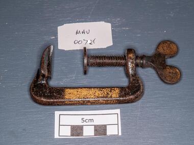
Tools, steel 'G' Clamp, early 20thC
A C-clamp or G- clamp is a type of clamp device typically used to hold a wood or metal work-piece, and often used in, but are not limited to, carpentry and welding. These clamps are called "C" clamps because of their C shaped frame, but are otherwise often called G-clamps or G-cramps because including the screw part they are shaped like an uppercase letter G. The fixed end is not adjustable so size is not variable. G-clamps are typically made of steel or cast iron, though smaller clamps may be made of pot metal. At the top of the "G" is usually a small flat edge. At the bottom is a threaded hole through which a large threaded screw protrudes. One end of this screw contains a flat edge of similar size to the one at the top of the frame, and the other end usually a small metal bar, perpendicular to the screw itself, which is used to gain leverage when tightening the clamp. When the clamp is completely closed, the flat end of the screw is in contact with the flat end on the frame When used some other object or objects will be contained between the top and bottom flat edges. A steel 'G' Clamp tools, g clamp, screws, steel, clamps, metalwork, woodwork, carpentry, early settlers, pioneers, market gardeners, moorabin, bentleigh, cheltenham -
 National Wool Museum
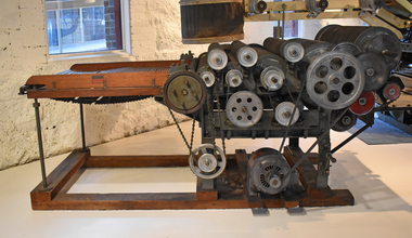
Machine - Carding Machine, CSIRO, 1960s
After scouring, the wool fibres are still tangled together. Carding untangles the fibres by brushing and straightening. The wool moves through a series of wire brush rollers that revolve at different speeds and in different directions to tease apart the wool. The fibres emerge from the machine as a continuous filmy web - called a sliver. The sliver must be thinned and divided into strands before the next process. Carding machines constantly require tuning. A highly skilled technician maintained and adjusted the speed of the rollers on the machine. This machine was developed by the CSIRO in the 1960s as a small-scale experimental machine. Industrial carding machines were four times the size of this one. Gold plaque on display with machine until 2018 read: G.H. Mitchell & Son, Adelaide have celebrated 125 Years of involvement with the Australian Wool Processing Industry by contributing the funds necessary to restore The Carding Machine, Noble Comb & The Gill Box. Also another gold plaque read: Experimental Carding Machine donated to The National Wool Museum by C.S.I.R.O Ryde has been rebuilt by Nick Sokolov of Comb Research & Development with the help of Bernard Tolan.Carder with small roller missing at coiling end. Driven by three horse power motor. Wooden slated feed table synchronised to overall gearing.carding machine, machines, wool industry, manufacturing, wool processing -
 Woodend RSL
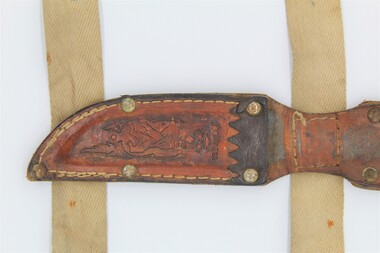
Knife sheath
This knife and scabbard belongs to Lindsay Fankhouser, who wore it on his ankle when he served as an engineer/ crewman in the RAAF (Iroquois and Hercules) during the Vietnam war. He used this knife many times a day while he was serving. It is a brown leather knife sheath, with a decorative front and two canvas straps attached at the back. The shorter strap is located at the bottom of the sheath and the longer strap is located just below the belt loop. Both straps are fixed in place with stitching. The top strap has a square of stitching, while the bottom strap has two lines of stitching that follows the stitching of the sheath. The belt loop is at the top of sheath and is a fixed flap of leather that is folded across the top and also holds the handle of the knife in place using a circular hole that fits around the butt of the knife. The bottom canvas strap has three adjustable brass male press studs on the left side as well as the fixed female one on the right. The top canvas strap has four adjustable brass male press studs on the right side as well as as the fixed female one on the right. The sheath is held together by stitching and five iron rivets. There is one on the point of the sheath, two on either side of the top, and two more 51mm below the top two. 46mm above the sheath, there are another two iron rivets on either side. Above that on the holding flap, there are two iron rivets just above the circular hole on either side. On the flap, around the hole there are three brass flat-headed split pins, one on either side and one on the front. At the top of the sheath, above the decorative embossing, there is a dark brown jagged cut strip of fixed leather. All the leather on the object is a reddish-brown, while the canvas and stitching is light beige. The end stitching on the canvas straps is dark grey. The front of the sheath is polished leather, while the back is rough.On back of belt loop flap, there is an embossd manufactuing patent number; PATENT Nr152.463 On face of the sheaf there embossed decoration. It depicts a lion with stylised decorative foliage and above the lion there is a fleur de lise. Above that it reads Soallingen Norge.norway, norge, soallingen, knife, small knife, hunting, scabbard, sheath, vietnam, lindsay fankhouser, raaf -
 Federation University Historical Collection
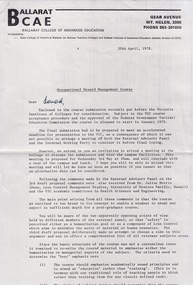
Document - Document - Correspondence, VIOSH: Ballarat College of Advanced Education; Submission put to the Victoria Institute of Colleges re Occupational Hazard Management Course, 1978, 1978
Victorian Institute of Occupational Safety and Health (VIOSH) Australia is the Asia-Pacific centre for teaching and research in occupational health and safety (OHS) and is known as one of Australia's leaders on the field. VIOSH has a global reputation for its innovative approach within the field of OHS management. VIOSH had its first intake of students in 1979. At that time the Institution was known as the Ballarat College of Advanced Education. In 1990 it became known as Ballarat University College, then in 1994 as University of Ballarat. It was 2014 that it became Federation University. VIOSH Australia students are safety managers, senior advisors and experienced OHS professionals. They come from all over Australia and industry. Students are taught active research and enquiry; rather than textbook learning and a one-size fits all approach. VIOSH accepts people into the Graduate Diploma of Occupational Hazard Management who have no undergraduate degree - on the basis of extensive work experience and knowledge. BCAE was submitting a proposal to the Victoria Institute of Colleges (VIC) for acceptance of the course in Occupational Hazard Management and the approval of the Federal Government Tertiary Education Committee for this course. If approval was received, after many submissions and adjustments, the course planned to start in January 1979. This was the First Intake of the course of VIOSH.Two type written pagesLetterhead of Ballarat College of Advanced Education. Signature of Derek Viner - Course Co-ordinator, School of Engineering. Hand written - Derek (Woolley)viosh, victorian institute of occupational safety and health, ballarat college of advanced education, submission, victoria institute of colleges, federal government tertiary education committee, first intake, derek viner, derek woolley -
 Flagstaff Hill Maritime Museum and Village
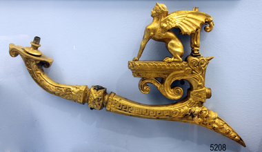
Functional object - Gas lamp wall bracket, Late 19th to early 20th Century
Gas lamps worked by heating something called a 'mantle' with a gas flame. The mantle then glowed brightly, lighting up the room. Lamps had either two chains, for a ceiling-mounted lamp or a tap for a wall-mounted burner to turn off the gas. These chains or taps could also adjust the flow of the gas and hence the brightness of the mantle. Before Carl Auer von Welsbach invented the gas mantle in the 1890s, all gas lights in homes and street lights had simple gas jets that pointed upwards. In the home, these lights were covered with glass globes and had an overall ornate look making the lamp ascetically pleasing and protecting the flame from being blown out. However, this arrangement was extremely inefficient: To get as much light as possible, the gas had to be turned fully up, resulting in large sheets of flame rising towards a ceiling. Also, because the lamp had to be point upwards, the illumination was directed upwards, i.e. at the ceiling rather than where it was needed. So the usable light for a given amount of gas was minimal but the invention of the gas mantle eventually changed this. It enabled gas lights to have a small flame and to direct their light downwards. The item is significant as it is part of a very ornate gas lamp wall bracket from the late 19th to early 20th century. Its provenance is currently unknown and at this time cannot be associated with a historical event, person or place and the item is assessed as a collective asset.Gas lamp wall bracket; part of a gas lamp. A single burner fancy wall mounted bracket, brass, ornate and decorative, featuring a Lamassu - figure with the body of a lion , wings of an eagle and human head. It was recovered from the wreck of the Loch ArdNoneflagstaff hill, warrnambool, flagstaff-hill, flagstaff-hill-maritime-museum, shipwreck-coast, flagstaff-hill-maritime-village, gas lamp, brass lamp, gas burner bracket, domestic artifact, gas lighting, gas lamp bracket -
 Melbourne Tram Museum
Drawing, Melbourne & Metropolitan Tramways Board (MMTB), "Cable Grip", Mar. 1934
Details the many components that went to make up a Melbourne cable tram grip. All drawings prepared by the MMTB. The second set has more components, generally bolts. See pdf files cable grip part 1, part 2 and part 3 for full details. R3485 - General Arrangement - provides a list of the parts Index - lists all the parts and relevant drawing number R3486 - Cable Grip Lever R3487 - Cable Grip Palm Handle R3488 - Cable Grip Pawl Rod Bracket and Bolt R3493 - Pawl Box, Guard Plate and Bolt R3494 - Pawl Latch Bracket R3496 - Adjusting Screw R3498 - Cable Grip Socket R3499 - Shoe and Shoe screws R3501 - Cable Grip Link R3502 - Quadrant R3503 - Crossbar R3504 - Slide and Slide end R3505 - Cheek R3506 - Protection Piece R3510 - Top Die Holder R3511 - Back Guard R3512 - Die R3513 - Bottom Die Holder R3514 - Sole Plate R3515 - Sheave R3518 - Swinger R3519 - Swinger Frame and Setscrew R3525 - Top Guide Plate R3534 - Sheave Protector R3535 - Sheave Centre R3541 - Hornbar WasherSet of 31 blueprint drawings within a brown paper folder and two brass fold back pins securing the drawings. Second copy - set of 38 drawings, black and white, loose in a sleeve. Has Mr Pratt on front cover. Date Stamped "6 Mar. 1934"trams, tramways, cable trams, cable grip, mmtb, lists -
 Ballarat Tramway Museum
Administrative record, Electric Supply Co. of Vic (ESCo), "One Man Cars", 11/1919
Set of records and items concerning the operation of one-man trams in Ballarat by the Electric Supply Co of Victoria, The North Melbourne Electric Tramways and Lighting Co (NMETL) and Bendigo trams. Comprises: 1 - Notes on Ballarat One Man Fare Box Cars - fares, tokens, style of trams, fare boxes, headways, and issues. The second page has operational statistics, insurance, and routes operated - dated 8/11/1919. 2 - Motorman's Daily Record Fare Box Car - small card 3 - Adjustment of Fares form 4 - Daily Report of Cars Inspected form 5 - Report of Accident or Unusual Occurance form 6 - Driver's Running Journal form 7 - Car Mileage form 8 - Driver's and Conductor's Cash Statement form 9 - Fare Box Cash Statements 10 - Colour pencil sketch plan view of front of tramcar 11 - two sheets "Cars in Service and Headway" - Keilor Road Route and River Route - NMETL 12 - Letter re times of a reported journey or trip and passenger numbers in Bendigo - pick up, numbers and running times for a Bendigo route - evening trip with a one-man tram. Yields information about the operation of fare box and one man trams in Ballarat, including notes on NMETL and Bendigo operations.Manila folder marked "One Man Cars" containing 12 items of various sizes with some folded to fit the folder. All pinned with a brass clip.tramways, trams, esco, one-man trams, forms, tokens, nmetl, bendigo -
 Flagstaff Hill Maritime Museum and Village
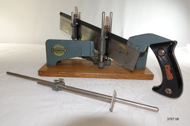
Tool - Mitre Saw Set, 1930-1955's
This Bodmann mitre saw set was used in the making of components for the ship model Sovereign of the Seas. It is part of a collection of objects used by Jim Williams, maker of fine ship models from about 1930-1955. Most of the components for the models, as well as many of the tools, were handmade by Jim Williams. Jim’s family has donated the ship model “Sovereign of the Seas” and many tools, accessories and documents used in the making of this and other ship models have been donated to Flagstaff Hill Maritime Village. ABOUT the BRAND NAME ON THE SAW - BODMANN and CO, Germany In 1927 the Brisbane Courier Mail described Bodmann and Co of Reinscheid, Germany as "manufacturers of guaranteed tools and hardware. It appears that at least the saw has been re-badges and sold by Bodmann because (1) there are remnants of a label on the saw blade similar in shape to the Bodmann label on the mitre set (2) the removed label reveals the name and logo of "ULMIA Schutz OTT Marke" (3) one of the "Bodmann" labels on the saw handle has been applied in a crooked manner, almost leaving off the last "N". ULMIA is a German manufacturer of high quality woodworking tools. A drawing of a very similar mitre bset with saw can be seen on the ULMIA website. In 2002 the long established company ANKE of Swabian Alb, Germany (makers of cut timber, workbenches and countertops) bought out the name and trademark rights of ULMIA. HISTORY OF SOVEREIGN OF THE SEA (brief) Ship model of HMS Sovereign of the Seas, scale model of 17th Century English war ship, was handmade and carved from plans, enclosed in airtight glass case. All components of that model, including even the smallest pulleys, were hand crafted using tools designed and made by Jim. Outstanding details include functional rigging and moving cannons. Please see our record 3732 of the mode Sovereign of the Seas for further details of the ship and the Jim Williams. This mitre saw set is connected with the hobby and skill of ship model making that has been crafted as a leisure activity for many generations. The hobby is often chosen by serving and retired mariners who appreciate the connection with maritime history. This mitre saw set was used by local Warrnambool man, Jim Williams, who was employed at Cramond and Dickson clothing store, and then at Fletcher Jones menswear for 27 years. It was used in making components for the model of the historic ship, the Sovereign of the Seas. The Sovereign of the Seas was a historic 17th century English war ship with important maritime heritage. Bodmann Mitre Saw set model 348, comprising metal, adjustable mitre saw on timber stand, and metal hand saw with Bakelite handle. The mitre saw is labelled with the trademark of Bodmann, Germany, and stamped with the model number 348. The saw has Bodmann trademark badges on each side of the handle; the text on one of these badges is not quite aligned. The saw blade has remnants of a label under which the stamped logo of ULMIA Schutz OTT Marke is clearly visible. Saw is fitted with two metal guides that slide onto vertical posts on the mitre saw. Metal measuring guide holds the wood job to the correct length. Saw has a protective brown paper wrapper. This mitre saw set is part of a collection of tools and accessories once used by Jim Williams, maker of a series of ship models 1930-1955 including “HMS Sovereign of the Seas”.On mitre saw- 2x logos "REGISTERED / BODMANN / TRADE MARK" and embedded stamp “348”. On saw - Remnant of logo on blade “ULMIA Schutz OTT Marke” with image of a church-like tall building, and 2x , "BEST QUALITY / BODMANN / MADE IN GERMANY” flagstaff hill, warrnambool, flagstaff hill maritime museum, maritime museum, shipwreck coast, flagstaff hill maritime village, great ocean road, jim williams, james bernard williams, ship model hobby, ship model tools, ship model making equipment, ship model making accessories, wood working tool, model making tool, mitre box set, mitre saw, bodmann and co reinscheid, germany, ulna ott of of swabian alb, germany, anke of swabian alb, germany, sovereign of the sea, ship model, hobby, ship model tool, mitre saw set -
 Warrnambool RSL Sub Branch
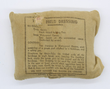
First Field Dressing, Military wound - compression bandage, OCTOBER 1942 - Manufacture: Johnson & Johnson Pty. Ltd., Sydney
donation source and providence unknown - common item issued to individual soldiers and carried in a pouch on their individual webbing. As an historic army It is also in very good condition. The 'First Field Dressing' has a khaki cotton cover with a single stitched opening flap on the right hand end of the cover. The 'Contents' and 'Directions for Use' are written on the front exterior as follows: FIRST FIELD DRESSING TO OPEN: Outer. Cotton Break thread holding flap Inner. Waterproof Covers Tear apart at the uncemented corner (indicated by arrow). CONTENTS: Two dressings in Waterproof Covers,each consisting of gauze stitched to a bandage and a safety pin. Directions for Use - Take the folded ends of the bandage in each hand, and, keeping the bandage taut, apply the gauze pad to the wound and fix the bandage. one dressing to be used for each wound. In each case of head wounds when respirators have to be worn, care should be taken to adjust the pad so that it does not interfere with the fit of the facepiece. DO NOT HANDLE THE GAUZE OR WOUND See physical descriptionuniform -
 Warrnambool RSL Sub Branch
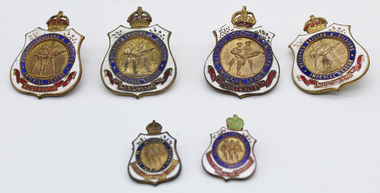
RSL BADGE COLLECTION _ Returned Sailors & Soldiers Imperial League Australia Badge and Returned Sailors' Soldiers' & Airmen's Imperial League Australia, RSL Membership Badges, Manufacturer - Stokes & Sons Melbourne for four badges, (Stokes closed in 1962). Small badges No 48030 (wiith 67 year clasp) has the makers inscription of - Property of League, Swann & Hudson VIC
donation source and providence unknown - common item issued to individual RSL Members across VictoriaAs an historic RSL Badge from WW1 & WW2 membership periods It is also in very good condition. The 'First Field Dressing' has a khaki cotton cover with a single stitched opening flap on the right hand end of the cover. The 'Contents' and 'Directions for Use' are written on the front exterior as follows: FIRST FIELD DRESSING TO OPEN: Outer. Cotton Break thread holding flap Inner. Waterproof Covers Tear apart at the uncemented corner (indicated by arrow). CONTENTS: Two dressings in Waterproof Covers,each consisting of gauze stitched to a bandage and a safety pin. Directions for Use - Take the folded ends of the bandage in each hand, and, keeping the bandage taut, apply the gauze pad to the wound and fix the bandage. one dressing to be used for each wound. In each case of head wounds when respirators have to be worn, care should be taken to adjust the pad so that it does not interfere with the fit of the facepiece. DO NOT HANDLE THE GAUZE OR WOUND Three x Large Badges (30mm (W) x 40mm (H) - With membership numbered on the rear of 45147, 70848, 74487 & 74642 stamped on the rear These badges a brass with white blue and red enamel inlay. The badge is in the shape of shield with a regal crown on top. The shield is white enamel, with a blue enamel circle (containing the words - Returned Sailors & Soldiers Imperial League. Below the circle a red enamel ribbon is depicted with the word - Australia enclosed. The brass centre of the badge has the figures of a Sailor & Soldier each carrying a rifle. Two x Small Badges (18mm (W) x 24mm (H) - The smaller badge has the same material and colours but includes the third figure of an Airmen holding a rifle in the centre. The location of the organisation name has changed to Returned Sailors' soldiers' & Airmen's in the blue circle and red ribbon contains - Imperial League Australia. One of the small badges has a green 67 year clasp fastened with three clasps around the crown. In this period Financial members received a new clasp for each year of financial membership. -
 Ballarat Tramway Museum
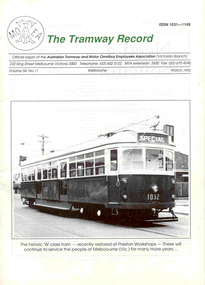
Magazine, Australian Tramway and Motor Omnibus Employees Association (ATMOEA), "The Tramway Record Vol. 54, No. 11, March 1992", Mar. 1992
Forty Four page, with glossy white cover and plain white paper inside - "The Tramway Record Vol. 54, No. 11 March. 1992" - with title in green ink and Australian Tramway and Motor Omnibus Employees Association logo on the front cover. Printed by the Victorian branch of the union. Features on the front cover a photo (see image) of the W7 1032. Other items featured are "Tram Stories" written by Frank Puls (Ballarat), pages 29 - 30, about his activities with the Ballarat Tramway Preservation Society, his liking for trams, training, incidents. Features a photo of Frank standing adjacent to No. 13 in Wendouree Parade and a photo taken on Christmas Day 1991, with an Explorer Coach driver. On page 31 - 36 traffic returns and wage comparisons over the years provided by Norm Maddock of The Tramway Museum, Stanhope St. Malvern. Shows cost of living adjustments to wages.trams, tramways, unions, melbourne, ballarat, btps, atmoea -
 Melbourne Tram Museum
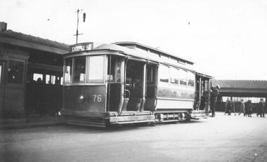
Photograph - Black & White Photograph/s, Lee A Ratten, c1925
Black and white photograph of tramcar 76 at Batman Avenue terminus in 1925. The tram is a single-truck California combination tram, one of 20 built for the P&MTT in 1915. The photo was taken at Batman Avenue in 1925 and shows a driver or conductor adjusting the trolley pole. The photo shows the Batman Ave terminus and Flinders St station in the background. Tram 76 was built in 1915 by the Meadow Manufacturing Co in Sydney for the Prahran and Malvern Tramways Trust before transferring to the MMTB in 1920. The J-class tram was bought by the SECV in 1931 and moved to Ballarat as tram No. 19. It operated in Ballarat until it was transferred to Bendigo in 1960 as tram No. 7, operating as public transport until 1972. It is now in operating condition at the Tramway Museum Society of Victoria in Bendigo. Tram 76 has the destination of Chapel St. Tram 76 was allocated at the Glenhuntly depot as at 24 March 1928.trams, tramways, batman ave, pmtt, secv, ballarat, bendigo, shelters, chapel st, tram 76, j class, mmtb -
 Geoffrey Kaye Museum of Anaesthetic History
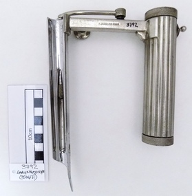
Tool - Laryngoscope, Magill, 1926
Ivan Magill (1888-1986) designer, this piece was designed in 1926 along with other anaesthetic equipment.Chrome plated straight complete Magill laryngoscope in medium size format, with attached light bulb. Cylindrical handle for battery deposit and with a wavy hand grip for easy handling. Serrated and screwed lids on top and base of the handle grip for insertion of batteries and checking of electrical contact stud. The handle also has a metallic switch without any instruction of use. The arm of the handle has a detachable screw to adjust extendable blade position and firmness. The light bulb is attached to a metallic tube connector to the handle arm which is just pressed to the contact point base. The blade has a oxidation spot under the blade. The piece in full has several scratches marks mostly founded in handle, arm and top blade areas. Two stamped inscriptions are present on the arm area, the manufacturer name and register number.Stamped on the arm of the handle lateral side, A.CHARLES KING Stamped on the arm of the handle opposite lateral side, REG. NO. 74901[9]magill, a. charles king ltd, regi. no. 749019, switch, laryngoscope -
 Bendigo Military Museum
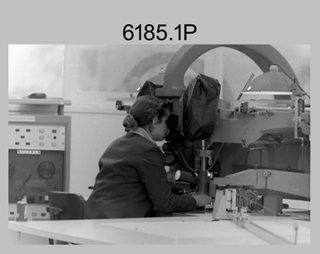
Photograph - Capturing Topographic Features with a Wild B8 – Army Survey Regiment, Fortuna, Bendigo, c1980
These four photographs of SPR Santina (Argetto) Straube capturing topographic features – plotting with a Wild B8 stereo plotter were most likely taken in c1980. Introduced in 1966, the Wild B8 stereo plotter was used for plotting topographic detail and contours. These analogue machines were manually controlled by adjusting the control knobs for the orientation of the 3D image. The B8s used a nine-inch square photo image on a film or glass diapositive which allowed highly accurate extraction of map features. At first, plotting by B8 and B9 equipment was undertaken at the aerial photography scale of 1:80,000 in pencil onto a controlled plotting sheet. Sheets were then inked up and reduced photographically to the 1: 100,000 publication scale for scribe impression production. In these photos SPR Santina (Argetto) Straube was plotting with a pencil or ink pen mounted at the far end of the pantograph arm. The plotting procedure was upgraded to direct plotting in ink with photographic reduction to publication scale. In 1975 four B8s were upgraded with tri-axis locaters as part of the Input Sub-system to enable digital extraction to AUTOMAP 1’s topographic database. When AUTOMAP 2 was introduced in 1982 these B8s were upgraded, and additional machines added to expand the Army Survey Regiment’s digital capture capability. This is a set of four photographs of a technician capturing topographic Features with a Wild B8 stereo plotter in Air Survey Squadron – Army Survey Regiment, Fortuna, Bendigo. 1980. The photographs were on 35mm negative film and were scanned at 96 dpi. They are part of the Army Survey Regiment’s Collection. .1) to .4) Photo, black & white, c1980. SPR Santina (Argetto) Straube operating a Wild B8 stereo plotter..1P to .4P – no annotations.royal australian survey corps, rasvy, army survey regiment, army svy regt, fortuna, asr, air survey, photogrammetry -
 Federation University Historical Collection
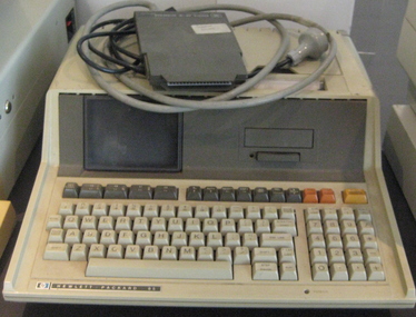
Equipment - Computer, Hewlett Packard, Personal Computer HP85A, 1979 (estimated)
The HP-85A was Hewlett Packard's first Series 80 microcomputer, introduced about 1979. It had a keyboard, a dual alpha/graphics monochrome display, a bidrectional alphanumerics and graphics printer, and mass storage tape drive all integrated into a marvelously designed and compact case. It's operating system was seemlessly integrated with a powerful BASIC programming language that included intuitive graphics and input/output capabilities. The HP-85A was also wonderfully expandable through four ports on the back of the case for adding plug in ROMS and modules. Specifications CRT DISPLAY Size: 12.7 cm (5 in.) diagonal Alphanumeric capacity: 16 lines x 32 characters Graphics capacity: 192 x 256 dots Scrolling capacity: 64 lines Character set: 256 characters; set of 128 + same set underscored Character font: 5 x 7 matrix Intensity: adjustable Cursor: underscore BASIC LANGUAGE AND OPERATING SYSTEM Standard ROM - 32K bytes Maximum add-on ROM - 48K bytes CRT memory RAM - 8K bytes USER READ/ WRITE MEMORY Standard - 16K bytes Maximum - 32K bytes TOTAL MEMORY Standard - 56K bytes Maximum - 120K bytes (Information from http://www.ebbsoft.com/hp/85a.htm)Personal computercomputers, monitor -
 Flagstaff Hill Maritime Museum and Village
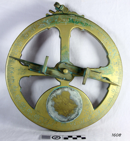
Instrument - Mariner's astrolabe
This representative example demonstrates a mariner’s astrolabe. Historical examples are rare. There are less than one hundred known to exist and most of these have been recovered from shipwrecks, many from Spanish and Portuguese vessels. An astrolabe is a measuring device once used to navigate the seas by observing the sun and stars to measure their altitude. The measurement of altitude could then be used to calculate the ship’s latitude but at that time in history there was no means of measuring longitude. The body of the navigational astrolabe was cast brass and much heavier, and less complicated than the variety used on land. The heavier weight and cut-away shape reduced the effect of the wind and waves when trying to use it at sea. A mariner’s astrolabe or ‘star finder’ is a simplified version than that used by Arabic astronomers to find the altitude of the sun and stars above the horizon, and time of the sunrise and sunset. It is a forerunner to the quadrant, octant and sextant and was popular for about 200 years over the 1500s and 1600s to find the latitude of a ship at sea. The user held the astrolabe at eye level and, usually with assistance, aligned the stars through the two small sights (pinnules), then read the altitude indicated by the pointer on the arm. It could also be used to sight the sun by holding it lower down, aiming it at the sun, and adjusting it until the sun shone through both pinnules. This astrolabe is an example used to demonstrate the mariner’s astrolabe, which was navigational tool of the 1500s and 1600s, in the time before longitude was able to be determined. It is a forerunner to modern navigation technology. Mariner’s astrolabe – a representative example. A gold painted, disc shaped object with cut outs and revolving arm in centre. The arm has two sights attached at right angles. The top has a ring attached. Measurements are marked in degrees in a circular scale around outer edge.flagstaff hill, warrnambool, maritime village, maritime museum, flagstaff hill maritime museum & village, shipwreck coast, great ocean road, navigation instrument, navigation tool, navigation, astrolabe, mariner’s astrolabe, measure latitude, measure altitude, arabic navigation, measuring device, star finder, astronomy, marine tool, marine instrument -
 Flagstaff Hill Maritime Museum and Village
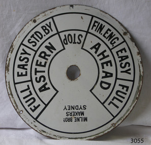
Equipment - Ships' Telegraph section, Milne Brothers, Copper and Brass Works, Early-to mid-20th century
This Engine Room section of a ship's telegraph system was part of the equipment of the Ports and Harbour ship the SS Rip. The vessel serviced and maintained the lights and buoys at Port Phillip Bay and Queenscliffe. The SS Rip was possibly the former gunboat "Albert". The ship’s communication system that was used from the late 19th century to early-to-mid-20th-century is called an Engine Order Telegraph (E.O.T.) or ship’s telegraph. The system has two parts, the Bridge Section and the Engine Room Section. The Bridge Section is usually mounted on top of a pedestal, and the Engine Room Section is often attached to a vertical surface. The standard commands printed or stamped onto the dial are the directions of AHEAD and ASTERN, and the speeds of STOP, FULL, EASY, STD. BY. and FIN. ENG. The ship’s pilot on the Bridge of a vessel sends his Orders for speed and direction to the to the Engine Room with the E.O.T. He moves the lever or levers, depending on the number of engines the ship has, to change the indicator on the Bridge Section’s dial to point in the new direction and speed of travel. This change causes the Orders to be duplicated on the Engine Room Section’s dial and a bell to signal the change simultaneously. The engineer then adjusts the ship’s engines and steering equipment to follow the pilot’s Order. The manufacturer, Mulne Bros., was a copper and brass works at 166 Sussex Street Sydney, in December 1892, and previously from 1870 at 128 to 130 Sussex Street. The company made and sold a wide range of equipment including machinery and gauges for the Railways.The Engine Room section is significant for being part of the communications system on the ship SS Rip, owned by Melbourne's Ports & Harbours department and used to service and maintain the navigation signals of Port Phillip Bay and at Queenscliffe in the mid-20th century. The dial is an example of marine equipment made in Australia and used for the safety of Victorian vessels. It is also significant for being made by an early Australian manufacturer, Milne Brothers of Sydney.Engine Room Section of a ship’s telegraph or Engine Order Telegraph (E.O.T.). The round metal dial has inscriptions stamped around the edges. The inscriptions are nautical terms for direction and speed and include the maker’s details. The dial was made by Milne Bros. of Sydney. It was part of the equipment on the "SS Rip" in Victoria.Black paint around dial: "MILNE BROS. / MAKERS / SYDNEY" "FULL EASY STD. BY " "FIN ENG. EASY FULL" ""ASTERN" "STOP" "AHEAD"flagstaff hill, warrnambool, maritime museum, maritime village, great ocean road, shipwreck coast, marine technology, marine communications, engine order telegraph, e.o.t., ship’s telegraph, bridge section, engine room section, ship’s engine telegraph section, marine telegraph, milne bros., milne brothers, sydney, copper and brass works, ports & harbours ship, ss rip, gunboat albert, service ship, maintenance ship -
 Bendigo Military Museum
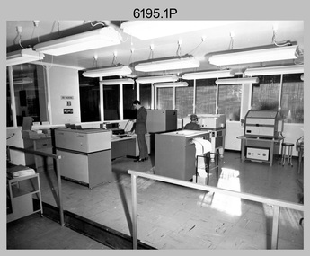
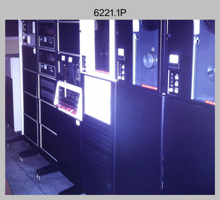
Photograph - Aerotriangulation Production – Army Survey Regiment, Fortuna, Bendigo, c1979
This collection of 19 photos was most likely taken in 1979 in Air Survey Squadron. The PDP 11/70 minicomputer shown photos .2P to .3P was the operating system introduced in 1977 as the mainframe system for the control of the APC4, aerial triangulation block adjustments, SORA OP Analytical Orthophoto control, APR Analytical Terrain Profile Recorder computation, graphics, and general computing. The Zeiss (Jena) Stecometer analytic stereocomparator for air photography shown in photos .5P to .9P was introduced at Air Survey Squadron in 1963. Aerotriangulation production was expedited using computers for analytical photogrammetric processes. The technician accurately measured between pass, tie, and survey control points on aerial photographs. The OMI/Nistri AP/C-3 analytical plotter shown in photos .10P and .11P was introduced in 1972–1973. Photo .11P shows a coordinatorgraph attached to the AP/C-3. The Zeiss D2 Planimat Stereoplotter shown in photo .12P was used for analytical orthophoto control. Wild PUG4 point transfer devices shown in photos .17P to .19P were introduced in c1968 superseding the PUG2 devices. PUG4 devices were used by technicians to stereoscopically view the photography containing the survey control points and the mapping aerial photography. The Control points were transferred from the control photography to the mapping diapositives of aerial photography by drilling their locations into the photographic emulsion.This is a set of 19 photographs of Air Survey Squadron personnel operating aerotriangulation equipment at the Army Survey Regiment at Fortuna, Bendigo, c1979. Black and white photos are on photographic paper and were scanned at 300 dpi. They are part of the Army Survey Regiment’s Collection. .1) - Photo, black & white, c1979, Aerotriangulation tasks, unidentified technicians. .2) to .3) - Photo, black & white, c1979, PDP-11 minicomputers tasks, unidentified technician. .4) - Photo, black & white, c1979, Aerotriangulation tasks, unidentified technician. .5) - Photo, colour, c1979, Zeiss (Jena) Stecometer, unidentified technician. .6) to.9) - Photo, black & white, c1979, Zeiss (Jena) Stecometer, unidentified technician. .10) - Photo, black & white, c1984, OMI/Nistri APC/3-1 analytical stereoplotter, SPR Kristin (Isaac) Skidmore. .11) - Photo, colour, c1979, OMI/Nistri APC/3-1 analytical stereoplotter, unidentified technician. .12) - Photo, colour, c1979, Zeiss D2 Planimat Stereoplotter, unidentified technician. .13) - Photo, black & white, c1979, Aerotriangulation tasks, unidentified technician. .14) - Photo, black & white, c1979, Aerotriangulation tasks, unidentified technician. .15) - Photo, black & white, c1979, Aerotriangulation tasks, CPL Ken Talbot-Smith .16) - Photo, black & white, c1979, Aerotriangulation tasks, SPR David Jobe. .17) - Photo, black & white, c1979, Wild PUG4 point transfer device, WO2 Brian Mead. .18) - Photo, black & white, c1979, Wild PUG4 point transfer device, CPL Andy Wilson. .19) - Photo, black & white, c1979, Wild PUG4 point transfer device, unidentified technician..5P is annotated ‘OMI-Nistri AP/C Analytical Plotter’ and ’Topo 36’. .12P is annotated ‘Zeiss Jena Stecometer Stereocomparator’ and ’Topo 35’. There are no annotations on the other photos.royal australian survey corps, rasvy, army survey regiment, army svy regt, fortuna, asr, aerotrig, air survey -
 Flagstaff Hill Maritime Museum and Village
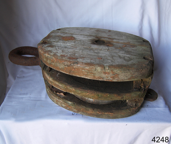
Equipment - Rope Block, Mid to Late 19th
A sailing block is single or multiple pulleys with one or more sheaves that are enclosed in an assembly between cheeks or chocks. In use, a block is fixed to the end of a line, to a spar, or a surface. A rope line is reeved through the sheaves, and maybe through one or more matching blocks at the far end, to make up what's known as a tackle. The purchase of a tackle refers to its mechanical advantage. In general, the more sheaves in the blocks that make up a tackle, the higher its mechanical advantage. The matter is slightly complicated by the fact that every tackle has a working end where the final run of rope leaves the last sheave. More mechanical advantage can be obtained if this end is attached to the moving load rather than the fixed end of the tackle. Various types of blocks are used in sailing. Some blocks are used to increase mechanical advantage and others are used simply to change the direction of a line. A ratchet block turns freely when a line is pulled in one direction but does not turn the other direction, although the line may slip past the sheave. This kind of block makes a loaded line easier to hold by hand, and is sometimes used on smaller boats for lines like main and jib sheets that are frequently adjusted. A single, large, sail-powered warship in the mid-19th century required more than 1,400 blocks of various kinds and sizes. An item from an old sailing vessel from the late 19th to early 20th century, unfortunately, the item cannot be identified as to what vessel it belonged to. It does however give an insight into a piece of sailing equipment that's design is still in use today on pleasure sailing craft. Wooden closed spelter double rope block with two pully's between sheaves, block has metal frame around outside of the sheaves and 4 metal pins, 2 each side of the frame at top and 2 at bottom, joining the sheaves together. The shaft between the sheaves is also wooden. Remnants of orange and black paint on outside of block. Shafts are chipped, wood has borer holes. (NOTE: Block was rediscovered after relocating objects to new storage area)Noneflagstaff hill, warrnambool, flagstaff hill maritime museum, maritime museum, shipwreck coast, flagstaff hill maritime village, great ocean road, sailing ship, pulley, block, sheave, ship equipment, rope block, sail rigging -
 Flagstaff Hill Maritime Museum and Village
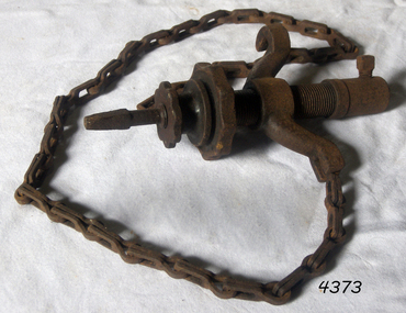
Tool - Chain Drill Attachment, Millers Falls Co, 1900-1931
An auxiliary tool for use with a breast drill or bit brace, when extra power is needed, or where pressure cannot be easily applied. The drill is automatically fed into the work by an adjustable friction feed which is automatically regulated by the resistance the drill encounters. These were made to fit on breast drills, and used for drilling metal, particularly round sections like a pipe. The chain is run around the object being drilled and gradually tightens as the hole is drilled, maintaining pressure while being a bit easier on the operator. Millers Falls Co. is a tool manufacturing company originally based in Millers Falls, Massachusetts, USA. It was established in Greenfield, Massachusetts in 1868 as Gunn & Amidon by Levi J. Gunn and Charles H. Amidon. Gunn and Amidon, along with a third partner, Henry L. Pratt built a factory in the north of Greenfield. After the Greenfield factory burned down, the company was reorganized as the Millers Falls Manufacturing Co. It merged with Backus Vise Co. in 1872 to form Millers Falls Co. In 1931 Millers Falls tools purchased the majority of the shares of Goodell-Pratt tools and merged with that manufacturer in 1932. In 1962 the company was acquired by Ingersoll Rand. In 1982, Ingersoll Rand sold the Millers Falls business to the newly created Millers Falls Tool Co. The company was head quartered in Alpha, New Jersey. Since 2002 the company trademark has belonged to Hangzhou Great Star Industrial, of Hangzhou, China. The item is associated with a tool manufacturing company established in the mid-19th century that pioneered the development of many types of tools used in many differing trades. The company grew to become a major supplier of tools around the world and today its tools that were produced during the mid-19th and early 20th centuries are now collectable items. Drill attachment with chain No 717 from 1925 catalogue 1/2 socket hole Millers Falls, Massachusettsflagstaff hill, warrnambool, flagstaff hill maritime museum, maritime museum, shipwreck coast, flagstaff hill maritime village, great ocean road, chain drill, mast drill, millers falls, drilling attachment, drilling tools -
 Flagstaff Hill Maritime Museum and Village
Equipment - Block, Late 19th to early 20th century
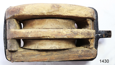
A sailing block is single or multiple pulleys with one or more sheaves that are enclosed in an assembly between cheeks or chocks. In use, a block is fixed to the end of a line, to a spar, or a surface. A rope line is reeved through the sheaves, and maybe through one or more matching blocks at the far end, to make up what's known as a tackle. The purchase of a tackle refers to its mechanical advantage. In general, the more sheaves in the blocks that make up a tackle, the higher its mechanical advantage. The matter is slightly complicated by the fact that every tackle has a working end where the final run of rope leaves the last sheave. More mechanical advantage can be obtained if this end is attached to the moving load rather than the fixed end of the tackle. Various types of blocks are used in sailing. Some blocks are used to increase mechanical advantage and others are used simply to change the direction of a line. A ratchet block turns freely when a line is pulled in one direction but does not turn in the other direction, although the line may slip past the sheave. This kind of block makes a loaded line easier to hold by hand and is sometimes used on smaller boats for lines like main and jib sheets that are frequently adjusted. A single, large, sail-powered warship in the mid-19th century required more than 1,400 blocks of various kinds and sizes.A historic item from an old sailing vessel from the late 19th to early 20th century, unfortunately. It represents part of the rigging required to set the sails on a wind-powered vessel.A two sheave wood sailing block with metal hook and becket. One sheave missing. flagstaff hill, warrnambool, shipwrecked-coast, flagstaff-hill, flagstaff-hill-maritime-museum, maritime-museum, shipwreck-coast, flagstaff-hill-maritime-village, block, sailing block, two-sheave block, 2 sheave wood block, marine technology, sailing equipment, rigging, rigging block -
 Flagstaff Hill Maritime Museum and Village
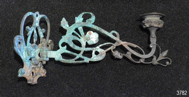
Domestic object - Candle Bracket, c. 1878
This candle bracket was recovered from the wreck of the sailing ship Loch Ard after the to the disaster in 1878. The bracket has been hand forged into a pleasing shape and design. The candle holder on the arm of the bracket cn swivel from side to side allowing the light to be adjusted. LOCH ARD 1873-1878 – The Scottish-built clipper ship Loch Ard was bound for Melbourne in 1878 with 54 people on board. The mixed cargo it carried included items for the 1880 International Exhibition in Melbourne, one of which was the now famous Majorca ware Minton ‘Peacock’ statue. The Loch Ard was wrecked on June 1st when the ship crashed into Mutton Bird Island, east of Port Campbell. The only survivors were Tom Pearce, a crew member, and Eva Carmichael, a young passenger who was rescued by Pearce. The Gibsons, owners of nearby Glenample Homestead, cared for Tom, and for Eva who stayed longer before returning to Ireland. The wreck of the Loch Ard was discovered in 1967, before the introduction of the Victorian historic shipwreck legislation. In 1969 it was decided that all recovered material should be lodged with the Receiver of Wrecks. In 1980 Flagstaff Hill Maritime Museum Divers received a permit to recover artefacts from the wreck to safeguard them from looters. In 1982 the site was listed as a Historic Shipwreck, and the Maritime Archaeology Unit recovered loose artefact material. The candle bracket is an example of light fittings from the ship ‘Loch Ard’ or from part of the ship’s cargo, imported for use in Colonial Victoria in the 19th to early 20th century. Flagstaff Hill’s collection of artefacts from LOCH ARD is significant for being one of the largest collections of artefacts from this shipwreck in Victoria. It is significant for its association with the shipwreck, which is on the Victorian Heritage Register (VHR S417). The collection is significant because of the relationship between the objects, as together they have a high potential to interpret the story of the LOCH ARD. The LOCH ARD collection is archaeologically significant as the remains of a large international passenger and cargo ship. The LOCH ARD collection is historically significant for representing aspects of Victoria’s shipping history and its potential to interpret sub-theme 1.5 of Victoria’s Framework of Historical Themes (living with natural processes). The collection is also historically significant for its association with the LOCH ARD, which was one of the worst and best known shipwrecks in Victoria’s history. Candle bracket, bronze with fancy floral design. Bracket has been hand wrought with varying widths of flat iron. Bracket’s arm swivels on a pin front of bracket. Bracket was recovered from the wreck of the Loch Ard. flagstaff hill, warrnambool, shipwrecked coast, flagstaff hill maritime museum, maritime museum, shipwreck coast, flagstaff hill maritime village, great ocean road, shipwreck artefact, loch ard, victoria, eva carmichael, tom pearce, antique, candle holder, candle bracket, candlestick holder, lighting, ship lighting, ship hardware -
 Puffing Billy Railway
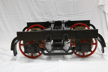
Bogie - Break of Gauge, Circa 1920
Designed and built in the early 1920’s by Charles Robert Prosser , a Melbourne Engineer, for an enquiry by the Commonwealth Government into ways of solving the break of gauge problem. Breaks or changes in railway gauges existed at most state borders of Australia during the first half of the 20th century. Upon completion of this model, it was placed on display in the Federal Parliament then located in Parliament House, Melbourne. Patents on the Break of Gauge Bogie Application number Title Applicant(s) Inventor(s) Filing date 1921000390 Improved means of adjusting the wheels of rolling stock to suit railway tracks of different gauges Charles Robert Prosser Charles Robert Prosser 1921-02-01 1917004843 Improvements in and connected with railway or other ticket supply tubes Charles Robert Prosser Charles Robert Prosser 1917-08-09 1915016191 IMPROVEMENTS IN AND CONNECTED WITH THE ADAPTATION OF RAILWAY ROLLING STOCK TO DIFFERENT GAUGES Charles Robert Prosser Charles Robert Prosser 1915-05-01 1915015980 Improvements in and connected with the adaptation of railway rolling stock to different gauges Charles Robert Prosser Charles Robert Prosser 1915-04-09 1914012931 Improvements in and connected with the adaptation of railway rolling stock to different gauges Charles Robert Prosser Charles Robert Prosser 1914-04-20 The Sydney Morning Herald Fri 2 Sep 1921 Page 6 BREAK OF GAUGE DEVICE. http://nla.gov.au/nla.news-article28088233 Historic - Railway Invention Break of Gauge Bogie Break of Gauge Bogie made of iron and wrought iron & brassboggie, break of gauge, puffing billy -
 Bendigo Military Museum
Photograph - Aerotriangulation Production – Army Survey Regiment, Fortuna, Bendigo, c1970s to 1980s
This collection of 14 photos was most likely taken in the 1970s and 1980s in Air Survey Squadron. The PDP 11/70 minicomputer shown in photo .1P was the operating system introduced in 1977 as the mainframe system for the control of the APC4, aerial triangulation block adjustments, SORA OP Analytical Orthophoto control, APR Analytical Terrain Profile Recorder computation, graphics, and general computing. Technicians used the Wild A9 Stereocomparator shown in photo .2P to accurately measure between pass, tie, and survey control points on aerial photographs. The Zeiss D2 Planimat Stereoplotter shown in photos .3P to .4P was used for analytical orthophoto control. It was introduced in 1972-1973 The Zeiss (Jena) Stecometer analytic stereocomparator for air photography shown in photos .5P to .11P and .14P was introduced at Air Survey Squadron in 1963. Aerotriangulation production was expedited using computers for analytical photogrammetric processes. The technician accurately measured between pass, tie, and survey control points on aerial photographs. Wild PUG4 point transfer devices shown in photos .12P to .13P were introduced in c1968 superseding the PUG2 devices. PUG4 devices were used by technicians to stereoscopically view the photography containing the survey control points and the mapping aerial photography. The Control points were transferred from the control photography to the mapping diapositives of aerial photography by drilling their locations into the photographic emulsion.This is a set of 14 photographs of Air Survey Squadron personnel operating aerotriangulation equipment at the Army Survey Regiment at Fortuna, Bendigo, c1970s to 1980s. Photographs .1P to .13P were on 35mm colour slide film and scanned at 96 dpi. Photograph.14P was printed on photographic paper and was scanned at 300 dpi. They are part of the Army Survey Regiment’s Collection. .1) - Photo, colour, c1979, PDP-11 minicomputer. .2) - Photo, colour, c1970s, Unidentified technician operating a Wild A9 Stereocomparator. .3) - Photo, colour, c1970s, Zeiss D2 Planimat Stereoplotter. .4) - Photo, colour, c1970s, Zeiss D2 Planimat Stereoplotter, unidentified technicians. .5) - Photo, colour, c1970s, Zeiss D2 Planimat Stereoplotter, SGT Christopher Wardley. .6) - Photo, colour, c1970s, Zeiss D2 Planimat Stereoplotter. .7) to.9) - Photo, colour, c1970, Zeiss (Jena) Stecometer, unidentified technicians. .10) to.11) - Photo, colour, c1988, SPR Toni Wright operating a Zeiss (Jena) Stecometer. .12) - Photo, colour, c1970s, Wild PUG4 point transfer device, SPR John Shepard. .13) - Photo, colour, c1970s, Wild PUG4 point transfer device, SPR David Edwards. .13) - Photo, colour, c1970s, Wild PUG4 point transfer device, SPR David Edwards. .14) - Photo, colour, c1980, Zeiss (Jena) Stecometer, SGT Bruce Hammond.Some of the equipment is annotated on the frame of the 35mm slides.royal australian survey corps, rasvy, army survey regiment, army svy regt, fortuna, asr, aerotrig, photogrammetry -
 Beechworth RSL Sub-Branch
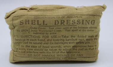
Shell Dressing, March 1944
Shell dressings were carried by individual soldiers, intended to be used as a first dressing in event of wounding or injury. Each cloth pack contains dressings comprised of a gauze pad stitched to a bandage and a safety pin. The field dressing was often the first line of treatment and was intended to be applied by the wounded man himself or other soldiersThis dressing is significant as a representative object carried by every soldier in WWII.Bandage covered in light brown cotton casing. Front side has inscription and instructions for use.Printed on cotton package containing the Shell Dressing. Inside a lined box. Commonwealth of Australia/ SHELL DRESSING / To Open /Outer Cover. Tear cover open at top between stitches. / Inner Waterproof Cover. Tear apart at the corner indicated by arrow. / DIRECTION FOR USE -Take the folded ends of/bandage in each hand, and keeping bandage taut, apply the/gauze pad to wound and fix bandages with safety pin./ In the case of head wounds, when respirators have to be worn, care should be taken to adjust the pad so that it / does not interfere with the fit of the face-piece. / DO NOT HANDLE WOUND OR PAD. / under a black line / Johnson & Johnson Pty, Ltd, Sydney/ MARCH 1944 On the reverse an adhesive sticker with the words "Lent by Lance Flynn" dressing, shell dressing, commonwealth of australia, johnson & johnson -
 Bendigo Military Museum
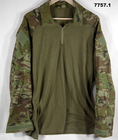
Uniform - SHIRT, TROUSERS - COMBAT DRESS ARMY, Australian Defence Industries, 2018
AMCU (Australia Multi Camouflage Uniform) Combat Dress colours - light to dark green through to mid to dark brown. Cotton/polyester fabric. Green colour plastic buttons. Nylon and metal zippers. 1. Shirt - polo style, with collar, long sleeves with adjustable velcro and strap at cuff. Two large sleeve pockets with hook and pile closure flaps, one small pocket left sleeve. Half zipper closure. Front and back of shirt - plain khaki colour knit fabric. No manufacturers label. 2. Trousers - waist band with belt loops, two front pockets, two large side pockets with zipper closure, two small pockets with hook and pile flap closure, zipper fly. White colour polyester fabric manufacturers label on right pocket lining. Green cotton fabric pocket lining. At ankle - elastic drawstring with plastic lock clip.Manufacturers information on label - black ink print. 2. "ADA/ MADE IN AUSTRALIA/ NOV 2018/ PO: CC36LD/ NSN:8415 66 161 6292/ SIZE: 34l/ 84-89 cm/^/ NAME/ PM KEYS NO:/ MAIN:/ 75% COTON/ 25% POLYESTER/ STRETCH/ 91% NYLON 9% ELASTANE/ KNEE PADS MUST BE REMOVED BEFORE/ CLEANING. HOT MACHINE/WASH. NO BLEACH/ NO FABRIC SOFTENERS/ MAY BE TUMBLE DRIED HOT/ DO NOT IRON OVER/ STRETCH PANELS OR HOOK AND PILE" .uniform, army, combat dress, amcu -
 Frankston RSL Sub Branch
Helmet, Australian M1, circa 1960's
Standard issue United States M1 pattern steel helmet, olive drab in colou, stretch cotton cargo type net, with fibreglass liner. On the inside of a strap in the liner '8415-153-6671' is printed in black ink. This number would appear to be the "Federal Stock Number (FSN)" which was used 1949 to 1975 when ti was replaced by "National Stock Number (NSN)' by additional of 00 after the first 4 numbers. this would indicate that it was made in USA. The chin strap and liner are both complete and fully operable. These helmets were first issued in 1941 to the United States Armed Forces. They were adopted after the Korean War by the Australian Defence Force. In the 1990s they were replaced by the Kevlar based Personnel Armour System-Ground Troop (PASGT) type helmet. However, as evidenced by this helmet, some M1 Steel helmets were not replaced in-service by the PASGT helmet and survived into the early 21st Century. Used by Royal Australian Army in Vietnam in areas where mines were significnat, such as Long Hai's mountains (together with US flak jackets), and also by Royal Australain Navy.An example of an Australian Army issue M1 steel battle helmet complete with fibreglass liner. This helmet type was issued to Australian defence personnel during the Vietnam conflict. The inner line has a transfer on the front " Australian Military Forces" with rising sun badge. The steel outer has an olive green elastic cover (similiar to cargo net) to hold camouflage material. The M1 is two "one-size-fits-all" helmets: an outer shell made of metal and a hard hat-type liner that is nestled inside the shell and contains the suspension system that would be adjusted to fit the wearer's head. Helmet covers and netting would be applied by covering the steel shell with the extra material tucked inside the shell and secured by inserting the liner. The helmet is 7 inches in height, width is 9.5 inches and length is 11 inches. The weight of a World War II era M1 is approximately 2.85 pounds including the liner and chinstrap. (From Wikipepedia) the inner line has a transfer on the front " Australian Military Forces" with rising sun badge.steel helmet -
 Flagstaff Hill Maritime Museum and Village
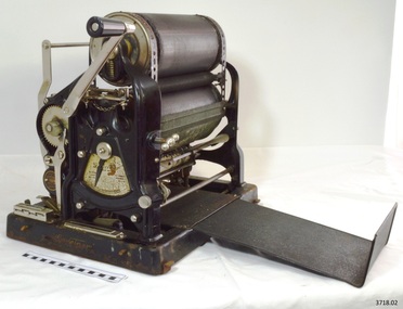
Gestetner Machine, c. 1922 - 1929
This Gestetner Cyclostyle duplicating machine was invented and manufactured by David Gestetner. He claimed in 1922, once he had released several models, that if a Gestetner Durotype stencil was used together with his Cyclostyle machine, then 10,000 copies could be made from the one Durotype stencil, an amazing claim for office technology of that era. David Gestetner (1854-1939), was born in Csoma, Hungary. He has been called the “founder of the worldwide office copying and duplicator industry.). He moved to London and in 1879 filed his first copying patent. In 1881 he patented the Cyclostyle stylus (or pen), which was used in conjunction with his Cyclograph device for copying text and images, He established the Gestetner Cyclograph Company in England at this time (1881) to protect his inventions and to produce his products; stencils, stylos (stylus or pen) and ink rollers. HIs inventions included nail-clipper and the ball-point pen (although the latter is more commonly associated with Laszlo Biro). Gestetner’s patented Cyclograph duplicator was used with his Cyclostyle Stylus or pen to write or draw on special thin wax-coated stencil paper (originally used for kite making paper) in the following way; 1. The Cyclostyle stencil was placed on a lower, framed metal plate of the Cyclograph 2. An upper frame was clipped over the top 3. The Cyclostyle pen, with its tip being a small metal-spiked or toothed wheel, was used to write or draw on the stencil, punched small holes into the paper and removed the wax coating in those places 4. The upper frame and stencil was then removed and a piece of blank paper was placed onto the metal plate in the lower frame and the upper frame with stencil was replaced 5. A roller was given an even distribution of Cyclostyle ink and rolled by hand over the stencil in the frame. This forced the ink through the holes in the stencil to and made a copy of the stencil on the paper 6. The upper frame was raised, the printed paper removed and another blank sheet was put into place. The whole process was repeated until enough copies were made. Gestetner’s invention developed further in 1894, with a stencil that could be placed on a screen on a revolving drum. The drum was manually rotated, the stencil then wrapped around another drum and was fed between cloth-covered rollers on which ink was evenly spread. Each revolution of the drum forced ink through the holes in the stencil and transferred the ink onto paper that had been fed between rollers and pressed against the drum. The process was repeated for each page. The paper was still fed and removed manually in this earlier invention but became more automatic in later models. In 1902 Gestetner duplicator model 6 was put onto the market. This model included the improvement of an automatic paper feed that synchronised with the rotation of the stencil. The Gestetner machine was the first office printing machine. It was easily installed and it made exact copies of the sane document quickly, effectively and inexpensively. This changed the way offices operated, making information easily available to many more users. The machines were commonly used in small businesses, schools, churches, clubs and other organisations for the wide distribution of a wide variety of information in the form of worksheets, newsletters and more. In 1906 the Gestetner Works were opened in Tottenham Hale, North London, and thousands of people were employed there up until the 1970’s. Due to the fast growing success of the Gestetner Duplicator machines many international branches for sales and service centres were established. David Gestetner was succeeded by his son Sigmund, followed by his grandson’s David and Jonathan. Further advancement was made by using a manual typewriter with specifically designed stencils. The end product was a printed, typewritten copy similar to the print from newspapers and booklets. In the next few years there were further developments of this revolutionary invention. The Gestetner Cyclostyle duplicator in our Collection is dated c.1922 - 1929 and it uses Gestetner Durotype stencils The 1922 British Industries Fair’s catalogue contained advertising for the Gestetner Rotary Cyclostyle “The World’s Premier Duplicator”, demonstrated at Stand K 86.” A Notice at the foot of the advertisement’s page boasts "Important - D Gestetner's latest invention, the "Durotype" Stencil, enables you to obtain 10,000 copies from one original if desired. It contains no wax of any description, is indestructible, can be stored indefinitely and printed from as required” In 1929 the look of the Gestetner machines changed; American designer Raymond Loewy was invited by Gestetner to improve the look of his duplicators, resulting in a very streamlined appearance. Eventually, around 1960’s, offices replaced their Gestetner with small photocopying machines and printers. Gestetner took over ownership of other office machine companies over time, including Nashua, Rex Rotary, Hanimex and Savin and eventually all came under the holding company name of NRG (Nashuatech, Rex Rotary and Gestetner). In 1996 Ricoh acquired the Gestetner Company, and it was renamed the NRG Group. REFERENCES Cyclostyle, Stencil Duplicating Machines, antique Copying Machines, Early Office Museum, http://www.officemuseum.com/copy_machines.htm Duplicating machines, Wikipedia Duplicator, Collection online, Canada Science and Technology Museums Corporation http://techno-science.ca/en/collection-research/collection-item.php?id=1989.0229.001 Gestetner duplicators, Totterham-Summerhillroad.com http://tottenham-summerhillroad.com/gestetner_duplicators_tottenham.htm Gestetner Duplicator, V&A Museum http://collections.vam.ac.uk/item/O322014/gestetner-duplicator-duplicator-loewy-raymond-fernand/ Gestetner, Grace’s Guide to British Industrial History, http://www.gracesguide.co.uk/Gestetner Duplicating machines such as this one revolutionalised access to copies of printed material, changing the way that educational bodies, offices, small businesses and community clubs and charities operated.Duplicating machine, Gestetner Cyclostyle Durotype, a stencil-method duplicating machine with two rotating drums plus rollers. Hand operated, tabletop office machine. Front has folding Bakelite handle, oil filling hole, calibrating gauge with scale, and copy counting meter. Right side has printed manufacturer’s plate that slides out as a paper output tray. Left side has metal plate with protrusions and perforations, plus another similar plate that is detached. It also has a metal frame attached [that would have been used to hold a paper input board, adjusted for various sizes of paper]. Cover, metal, with folding wooden handle on top, attaches to base with metal clips. Inscriptions printed on machine, mostly in gold-coloured paint. Round metal manufacturing plate is stamped with Serial Number 95759. Made by D. Gestetner, London, c.1922-1929Maker’s plate “MANUFACTURED / BY / D. GESTETNER LTD, / No. 95759 / CYCLOSTYLE WORKS / TOTTENHAM HALE / LONDON, N” Copy counting meter shows “1 4 6 4 8 [space]“ copies. Calibrating gauge has divisions with numbers “0 1 2“, labelled “← [left arrow] “TO PRINT LOWER” and “→ [right arrow], TO PRINT HIGHER”. “The Gestetner”, “Cyclostyle”, “Gestetner” (Trade Mark), Right side print of manufacturing details includes “The / Gestetner / TRADE MARK” And “THE FOLLOWING TRAFE MARKS / - - - OF INK, STENCILS / - - - AND GUARANTEE OF PERFECT / - - - BOTH - - - AND MACHINE” and “CYCLOSTYLE / DUROTYPE / GESTETNER” and “D. Gestetner” flagstaff hill, warrnambool, shipwrecked coast, flagstaff hill maritime museum, maritime museum, shipwreck coast, flagstaff hill maritime village, great ocean road, office machine, copying machine, gestetner machine, duplicating machine, duplicator, stencil machine, gestetner cyclograph company, cyclograph, cyclostyle, d. gestetner ltd, gestetner durotype stencils, gestetner cyclostyle, printing machine, office technology, durotype stencils, david gestetner, raymond loewy, roneo, rotary duplicatorten, mimeo, mimeograph machine, roneograph copier -
 Kiewa Valley Historical Society
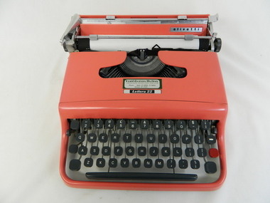
Typewriter Mechanical Portable, 1950s
The Olivetti company was founded in Italy in 1908.This particular typewriter is a Olivetti Lettera 22, oblique front stroke and portable manufactured after 1950. The 1950s and 1960s was a time when British manufactured goods were still purchased by many Australian consumers. The later 1960s onwards, there was a shift, mainly in the cities, to European made goods. The invasion of Japanese manufactured goods was relatively slower, especially in rural areas. The demand for long lasted and dependable merchandise was in the rural area still the most important criteria. The ease of setting up this typewriter and its compact mobility was its major benefit to trades people and travelling professionals, e.g. rural doctors, other medical professionals, accountants, lawyers and educators. This item facilitated the growing numbers of professional nomads requiring a relatively light office stationery package e.g. travelling novelist, writer, businessman and academics. This typewriter needed no electrical or battery power to operate it. Outback Australia, where at this point in time, was still relatively isolated from a good available electrical power reticulation and battery power, and therefore could not be totally measured as a highly efficient office environment.Although this typewriter was purchased from a business in Penrith, Sydney, N.S.W., it is significant that it travelled easily to the Kiewa Valley, demonstrating the mobility of certain sections of the community. This typewriter was designed by an Italian industrial designer, Marcello Nizzoli, in line with the art deco style of the 1930s and the colour and flexibility of the vibrant 1950s. The underlying theme of manufacturing in the 1950s was to produce equipment that was more efficient than what was inherited from the earlier period of 20th century. Improvements were made to this Olivetti typewriter by Giuseppe Beccio by reducing the number of parts made from 3,000 to 2,000. This reduction of parts and therefore cost of production was the major principle of the Japanese manufacturing juggernauts of the post World War II era. Efficiency and low costs material was becoming prime factors in the success of rural industries from the 1960s. Competition from overseas producers was starting to affect rural industries and the removal of the large range of tariff protection, especially rural products, required not only a shift of farm management but a more efficient cost savings modus operandi. This Olivetti Lettera 22, oblique front stroke portable (weighs 4kg) mechanical typewriter has a coral coloured plastic casing. The keys are made of black hardened plastic with white lettering, numbers and symbols (imperial fractions, and pound). It has a QWERTY keyboard as opposed to the Italian QZERTY. It has a lever to move the ribbon between black, neutral (for mimeograph stencils)and red colours (a red key is provided for highlighting specific words,letters or symbols) . This machine is fitted with only a black ribbon. It has a black rubber paper rollers and chromed metal parts on the carriage way. It has four rubber feet underneath the main body. On the left side of the roller there is a lever to adjust the roller from fixed (when mobile) through 1,2 and 3 line space gradients. This model has a key for zero but not one for the number one (uppercase letter l is used) see KVHS 0459 for the carrying bag.On the cover over the ribbon wheels letter strikers has a plate marked "Lettera 22" and the back plate behind the paper roller and in front of the paper supports has a silver metal label marked "olivetti made in great britain".commercial, mobile office equipment, mechanical typewriter -
 Bendigo Historical Society Inc.
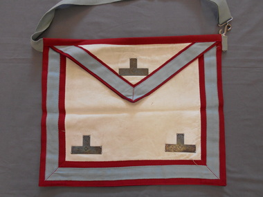
Ceremonial object - JOHN FREDERICK HARPER COLLECTION: LODGE APRON, 1950 - 1990's
Object. Soft white kid leather rectangle - 29 cm x 25 cms, outlined with a 1 cm wide red ribbon frame, a 2.5 cm blue frame, and a further 1 cm red frame. A metal lodge symbol, 6.5 cm x 3.5 cm is stitched onto the lower corners. A Vshaped is hanging panel overlaps the leather panel. and is stitched into the waistband, and hangs freely. The Vshape is edged by a 2.5 cm wide pale blue grosgrain ribbon, and the ribbon is, in turn, edged with a fine red border. This hanging panel is made from white kid leather, and has a Tshaped metal panel stitched at the centre front, and at the two lower corners. A 3 cm wide cotton tape has a silver coloured metal loop at one end, and a silver coloured Sshaped hook on the end of a 58 cm long, adjustable waistband, to fasten the apron around the waist of the wearer.organisation, masonic lodge, kid leather apron