
Showing 98 items matching " aerial survey of victoria"
-
 Bendigo Historical Society Inc.
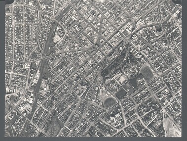
Photograph - WES HARRY COLLECTION: AERIAL VIEW OF BENDIGO CBD, 1966
... ... Aerial Survey of Victoria...PLACE Aerial view of bendigo cbd Bendigo CBD Aerial Survey of Victoria Aerial photograph of the Bendigo CBD. ...Aerial photograph of the Bendigo CBD. On the reverse is written : 'City of Bendigo 1966, State aerial Surveyplace, aerial view of bendigo, cbd, bendigo cbd, aerial survey of victoria -
 Bendigo Historical Society Inc.
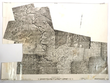
Map - FRED COWIE COLLECTION: AERIAL MAPS OF HEATHCOTE/EPPALOCK
... Map, Heathcote A3, Aerial Survey of Victoria, Photo-map prepared by Department of Crown Lands.Campaspe River , Wild Duck Creek, Knowsley, Eppalock Weir.Fred Cowie,46 McIvor Rd ,Bendigo....MAP Heathcote Fred Cowie Map, Heathcote A3, Aerial Survey of Victoria, Photo-map prepared by Department of Crown Lands.Campaspe River , Wild Duck Creek, Knowsley, Eppalock Weir.Fred Cowie,46 McIvor Rd ,Bendigo. ...Map, Heathcote A3, Aerial Survey of Victoria, Photo-map prepared by Department of Crown Lands.Campaspe River , Wild Duck Creek, Knowsley, Eppalock Weir.Fred Cowie,46 McIvor Rd ,Bendigo.map, heathcote, fred cowie -
 Bendigo Historical Society Inc.
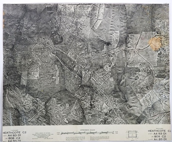
Map - FRED COWIE COLLECTION: AERIAL MAPS OF HEATHCOTE/EPPALOCK, 28-9-1960
... Map, Heathcote C2, Township of Heathcote, Melbourne Road through town branching off to Bendigo & Echuca. Aerial Survey of Victoria. Photo-map prepared by Department of Crown Lands and Survey from photographs taken in 1960. ...MAP Heathcote Fred Cowie Central Plan Office Map, Heathcote C2, Township of Heathcote, Melbourne Road through town branching off to Bendigo & Echuca. Aerial Survey of Victoria. Photo-map prepared by Department of Crown Lands and Survey from photographs taken in 1960. ...Map, Heathcote C2, Township of Heathcote, Melbourne Road through town branching off to Bendigo & Echuca. Aerial Survey of Victoria. Photo-map prepared by Department of Crown Lands and Survey from photographs taken in 1960. Copied photographically at the Central Plan Office.Fred Cowie,46 McIvor Rd,Bgo..Central Plan Officemap, heathcote, fred cowie -
 Bendigo Historical Society Inc.
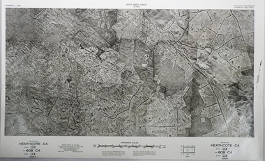
Map - FRED COWIE COLLECTION: AERIAL MAPS OF HEATHCOTE/EPPALOCK, 28-9-60
... Map, Heathcote C4, Aerial Survey of Victoria,Photo-map prepared by Department of Crown Lands and Survey from photographs taken in 1960. ...Map, Heathcote C4, Aerial Survey of Victoria,Photo-map prepared by Department of Crown Lands and Survey from photographs taken in 1960. ...Map, Heathcote C4, Aerial Survey of Victoria,Photo-map prepared by Department of Crown Lands and Survey from photographs taken in 1960. Copied photographically at the Central Plan Office.Date 28-9-60,C.P.O.Neg.No.21590.Scale 4 inches to 1 mile. Fred Cowie,46 McIvor Rd,Bgo..Central Plan Office.map, heathcote, fred cowie -
 Bendigo Historical Society Inc.
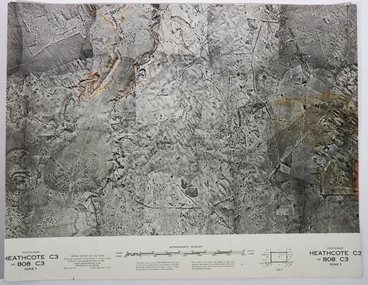
Map - FRED COWIE COLLECTION: AERIAL MAPS OF HEATHCOTE/EPPALOCK, 28-9-60
... Map, Heathcote C3, Aerial Survey of Victoria, Photo-map prepared by Department of Crown Lands and Survey from photographs taken in 1960.Copied photographically at the Central Plan Office. ...Map, Heathcote C3, Aerial Survey of Victoria, Photo-map prepared by Department of Crown Lands and Survey from photographs taken in 1960.Copied photographically at the Central Plan Office. ...Map, Heathcote C3, Aerial Survey of Victoria, Photo-map prepared by Department of Crown Lands and Survey from photographs taken in 1960.Copied photographically at the Central Plan Office. Date 28-9 60, C.P.O.Neg. No.21588.Campaspe River, Coliban River. Flower Hill. Fred Cowie,46 McIvor Rd.Bendigo (Not located 29.9.2022)Central Plan Office.map, heathcote, fred cowie -
 Glenelg Shire Council Cultural Collection
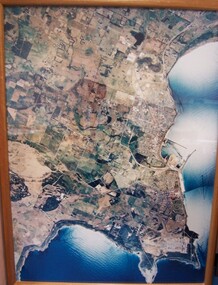
Photograph - Photograph - aerial view of Portland, 1988
... Portland Dec. 1988. aerial photography central Portland Portland Harbour Front: (no inscriptions) Back: (no inscriptions) Aerial view of the "City of Portland" and surrounding rural area to a scale of 1:10,000 Aerial Photomosaic of Portland Bay, 1988 Photograph Photograph - aerial view of Portland Division of Survey & Mapping, Department of Property & Services, Government of Victoria ...Census Project No. 1995. Portland Dec. 1988.Aerial view of the "City of Portland" and surrounding rural area to a scale of 1:10,000 Aerial Photomosaic of Portland Bay, 1988Front: (no inscriptions) Back: (no inscriptions)aerial photography, central portland, portland harbour -
 The Beechworth Burke Museum
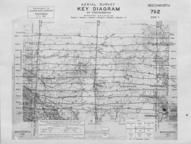
Photograph - Aerial Survey, 5/9/1947
... aerial survey...beechworth...burke museum...department of lands and survey...victoria...This image is an Aerial Survey, Key Diagram of Beechworth and surrounding area. Issued by Department of Lands and Survey, Victoria in 1947. ...Obverse: AERIAL SURVEY, KEY DIAGRAM OF PHOTOGRAPHS, APPROXIMATE SCALE OF MILES / DEPARTMENT OF LANDS AND SURVEY VICTORIA 5.9.1947. ...This image is an Aerial Survey, Key Diagram of Beechworth and surrounding area. Issued by Department of Lands and Survey, Victoria in 1947. ...This image is an Aerial Survey, Key Diagram of Beechworth and surrounding area. Issued by Department of Lands and Survey, Victoria in 1947. Photographed at an average height of 12300 feet above sea level, areas depicted are; Beechworth, Stanley, Bruarong, Baranduda, Muagegonga, Myrtleford, Everton, Wooragee North Tarrawinge, Dederang, Kergunyah North, Kergunyah, Yackandandah, El-Dorado, Barambogie, Murmungee, Barwidgee, Oxley, CarraragarmungeeBlack and white rectangular photograph. Image is printed on matt photographic paper and has a white un-printed border. Obverse: AERIAL SURVEY, KEY DIAGRAM OF PHOTOGRAPHS, APPROXIMATE SCALE OF MILES / DEPARTMENT OF LANDS AND SURVEY VICTORIA 5.9.1947. BEECHWORTH 792 ZONE 7. Reverse: BMM7010.1 (written in pencil) aerial survey, beechworth, burke museum, department of lands and survey, victoria, 1947 -
 Ringwood and District Historical Society
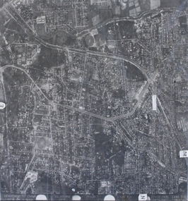
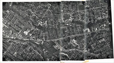
Photograph, Aerial photograph of Heathmont, Victoria - c.1960s, 1975
... Survey Melbourne, Project Run 31A 27-12-1975, Lens 209 1951M ASL. Aerial view of Heathmont - black and white photograph on chipboard backing. (Protected by slightly damaged plastic cover which could be removed for clearer image.) Aerial photograph of Heathmont, Victoria ...Aerial view of Heathmont - black and white photograph on chipboard backing. (Protected by slightly damaged plastic cover which could be removed for clearer image.)Department of Crown Lands and Survey Melbourne, Project Run 31A 27-12-1975, Lens 209 1951M ASL. -
 Ringwood and District Historical Society
Photograph, Composite Aerial Views of Ringwood, Victoria - 1972
... Survey. Maroondah Highway Project - Run 3 - 20.1.72 - 3,900' ASL. Two composite black & white aerial photographs with north-facing view over Maroondah Highway, including Railway Station precinct, Civic Centre precinct, Eastland, Mount Dandenong Road, Bedford Road, Ringwood Street, Warrandyte Road, Mullum Road, Loughnan's Road. Composite Aerial Views of Ringwood, Victoria ...Two composite black & white aerial photographs with north-facing view over Maroondah Highway, including Railway Station precinct, Civic Centre precinct, Eastland, Mount Dandenong Road, Bedford Road, Ringwood Street, Warrandyte Road, Mullum Road, Loughnan's Road.Department of Crown Lands and Survey. Maroondah Highway Project - Run 3 - 20.1.72 - 3,900' ASL. -
 Ringwood and District Historical Society
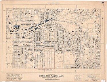
Map - State Aerial Survey, Dandenong Ranges Area, Parishes of Warrandyte and Ringwood - 1956
... Survey, July 1956, from aerial photographs and Cadastral Survey information. Subsequent hand-drawn addition of streets showing layout of "Township of Ballyduffy Estate 1858-60", an earlier proposed subdivision that did not eventuate. (See attached 5009b Ballyshanassy_ Melbourne’s lost suburb.pdf for Ballyduffy historical naming relevance). Ballyduffy Estate streets include City Road, West Prussia Road, Duffy Street, Ireland Street, Evans Street, Victoria...Survey, July 1956, from aerial photographs and Cadastral Survey information. Subsequent hand-drawn addition of streets showing layout of "Township of Ballyduffy Estate 1858-60", an earlier proposed subdivision that did not eventuate. (See attached 5009b Ballyshanassy_ Melbourne’s lost suburb.pdf for Ballyduffy historical naming relevance). Ballyduffy Estate streets include City Road, West Prussia Road, Duffy Street, Ireland Street, Evans Street, Victoria ...Map of central and southern areas of Ringwood and part of Ringwood East and Heathmont compiled by Dept of Lands and Survey, July 1956, from aerial photographs and Cadastral Survey information. Subsequent hand-drawn addition of streets showing layout of "Township of Ballyduffy Estate 1858-60", an earlier proposed subdivision that did not eventuate. (See attached 5009b Ballyshanassy_ Melbourne’s lost suburb.pdf for Ballyduffy historical naming relevance). Ballyduffy Estate streets include City Road, West Prussia Road, Duffy Street, Ireland Street, Evans Street, Victoria Street, Regina Street, Short Road, Prussia Road, Duffy Street East, Ireland Street East, Evans Street East, Chapman Street. Misc Topo 93 Sheet 22, Ringwood A4B2. Scale: 4 chains to 1 inch. Contour interval 20 feet. -
 Greensborough Historical Society
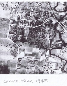
Photograph - Aerial Photograph, Victoria. Department of Lands and Survey, Grace Park 1945, 1945
... Aerial photo of Grace Park 1945, borders include Henry Street, Nepean Street, Grimshaw Street, and Plenty River. aerial 1945 Greensborough grace park melbourne aerial 1945 Laminated black and white aerial photo, 2 copies Grace Park 1945 Photograph Aerial Photograph Victoria. Department of Lands and Survey ...Aerial photo of Grace Park 1945, borders include Henry Street, Nepean Street, Grimshaw Street, and Plenty River.Laminated black and white aerial photo, 2 copiesaerial 1945, greensborough, grace park, melbourne aerial 1945 -
 Ringwood and District Historical Society
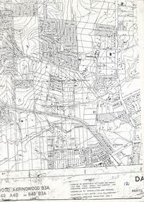
Map, Heathmont/Bayswater Area Survey Map - 1956
... Survey July 1956, from aerial photographs and cadastral survey informaton. Controlled by triangulation and traverse. Elevations in feet. Datum. L.W.M. Williamstown. Transverse , Mercator Projection. Zone 7." Cutaway section of black & white Dandenong Ranges Area survey map with countour lines centred over Bedford Road and Canterbury Road, Heathmont, and Bayswater Road and Wantirna-Sassafras Road (Mountrain Highway) Bayswater, Victoria. ...Cutaway section of black & white Dandenong Ranges Area survey map with countour lines centred over Bedford Road and Canterbury Road, Heathmont, and Bayswater Road and Wantirna-Sassafras Road (Mountrain Highway) Bayswater, Victoria. Chivers property marked on Armstrong Road, Heathmont.Caption: "Compiled by Department of Lands and Survey July 1956, from aerial photographs and cadastral survey informaton. Controlled by triangulation and traverse. Elevations in feet. Datum. L.W.M. Williamstown. Transverse , Mercator Projection. Zone 7." -
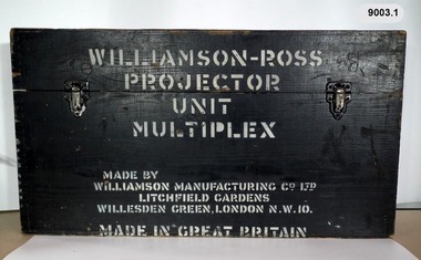 Bendigo Military Museum
Instrument - Multiplex Unit Projector, Williamson Manufacturing Co, Circa 1950
... aerial photography, however was restricted to each strip rather than between strips in the block. Although the Multiplex was phased out of production in 1968, it was used in the training of photogrammetry and aero-triangulation at the School of Military Survey located at Bonegilla, Victoria until the early 1990s. ...aerial photography, however was restricted to each strip rather than between strips in the block. Although the Multiplex was phased out of production in 1968, it was used in the training of photogrammetry and aero-triangulation at the School of Military Survey located at Bonegilla, Victoria until the early 1990s. ...Multiplex mechanical stereoplotting equipment was used at the Army Survey Regiment, Fortuna Bendigo. c1950s. Multiplex equipment was imported from the UK in 1951 and introduced in the following year, to accelerate map production output covering CMF training areas at 1:25,000 map scale. Multiplex plotting was a productive advancement replacing the ‘Arundel’ method of graphical plotting planimetric detail that was expensive and slow, especially in timbered mountainous terrain. Air photos were made into small diapositives and mounted on racks in the exact position relative to when the aerial photos were taken. The technicians operated the Multiplex in a darkened room, with one photo projected with a green filter and the other through a red filter to form a 3D view of the overlapping photos. The 3D model projected onto a platen, which was a small platform that was raised up and down. The technician viewed the 3D image with special glasses fitted with red and green lenses. In the centre of the platen was a small pinhole that served as a floating mark, with a vertical pencil located exactly below the pinhole. This tracing table was moved to follow the topographic feature or contour line and draw it on the paper underneath. The technician raising or lowering the platform’s floating mark to match the height of the 3D terrain. It also replaced the slotted template method of mechanical adjustment of strips of aerial photography, however was restricted to each strip rather than between strips in the block. Although the Multiplex was phased out of production in 1968, it was used in the training of photogrammetry and aero-triangulation at the School of Military Survey located at Bonegilla, Victoria until the early 1990s. The history of the Multiplex is covered in more detail with additional historic photographs, in pages 50 to 51 of Valerie Lovejoy’s book 'Mapmakers of Fortuna – A history of the Army Survey Regiment’ ISBN: 0-646-42120-4. This instrument is only one of the projectors of a set and is unfortunately missing its platen, coloured filters and coloured glasses. A cardboard set of glasses is included as an example. Another Multiplex instrument is in the collection as Item 9039.4A black wooden box containing a Multiplex Unit Projector (incomplete). The Multiplex has a Lamp Head, Barrel Housing, Body of the Projector and a Platen which is missing. .1 Protective wooden box .2 Multiplex Instrument .3 Multiplex Instrument Parts Diagram .4 A bank of Multiplex projectors in operation WILLIAMSON MANUFACTURING CO, PHOTOGRAPHIC ENGINEERS, SERIAL NUMBER 3437, TYPE MPC, LITCHFIELD GARDENS, LONDON AND READING.royal australian survey corps, rasvy, fortuna, army survey regiment, army svy regt -
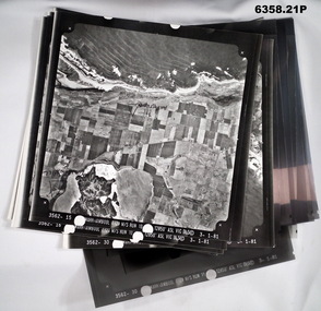 Bendigo Military Museum
Photograph - Aerial Photography - Mohogany Ship Search Warrnambool Victoria, Victorian Lands Department, 3.1.1981
... These Victorian Lands Dept Aerial Photographs were acquired by the Army Survey Regiment to help locate a Mohogany Ship wreck near Warrnambool Victoria as part of a unit Regimental Training Exercise...These Victorian Lands Dept Aerial Photographs were acquired by the Army Survey Regiment to help locate a Mohogany Ship wreck near Warrnambool Victoria as part of a unit Regimental Training Exercise Royal Australian Survey Corps RASvy Fortuna Army Survey Regiment Army Svy Regt ASR Seven Aerial photographic Prints and Film Negatives and positives of the same images. ...These Victorian Lands Dept Aerial Photographs were acquired by the Army Survey Regiment to help locate a Mohogany Ship wreck near Warrnambool Victoria as part of a unit Regimental Training ExerciseSeven Aerial photographic Prints and Film Negatives and positives of the same images. Images are Numbered 3562- 15,16,17,18,19, 29 and 30.royal australian survey corps, rasvy, fortuna, army survey regiment, army svy regt, asr -
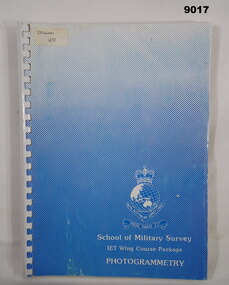 Bendigo Military Museum
Manual - School of Military Survey - IET Wing course Package Photogrammetry, School of Military Survey, Bonegilla, Victoria, 1987
... aerial photographic interpretation. Royal Australian Survey Corps RASvy Fortuna Army Survey Regiment Army Svy Regt ASR School of Military Survey SMS "DUGGAN 4/87" A4 blue and white coloured light card covered collection of 21x Precis held together with plastic ring binding. School of Military Survey - IET Wing course Package Photogrammetry Manual School of Military Survey - IET Wing course Package Photogrammetry School of Military Survey, Bonegilla, Victoria ...This is a collection of 21 x School of Military Survey Precis produced as a package to instruct Initial Employment Trainees (IET) on Photogrammetry. This set was produced for the IET Couse 4/1987 and was used by Spr Mick Duggan on that course. The Precis cover the operation of the Wild B8 Stereoplotter and aerial photographic interpretation.A4 blue and white coloured light card covered collection of 21x Precis held together with plastic ring binding. "DUGGAN 4/87"royal australian survey corps, rasvy, fortuna, army survey regiment, army svy regt, asr, school of military survey, sms -
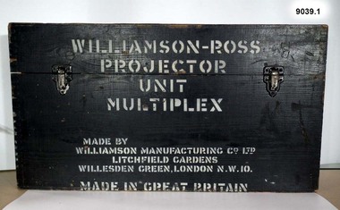 Bendigo Military Museum
Instrument - Multiplex Unit Projector, Williamson Manufacturing Co, Circa 1950
... aerial photography, however was restricted to each strip rather than between strips in the block. Although the Multiplex was phased out of production in 1968, it was used in the training of photogrammetry and aero-triangulation at the School of Military Survey located at Bonegilla, Victoria until the early 1990s. ...aerial photography, however was restricted to each strip rather than between strips in the block. Although the Multiplex was phased out of production in 1968, it was used in the training of photogrammetry and aero-triangulation at the School of Military Survey located at Bonegilla, Victoria until the early 1990s. ...Multiplex mechanical stereoplotting equipment was used at the Army Survey Regiment, Fortuna Bendigo. c1950s. Multiplex equipment was imported from the UK in 1951 and introduced in the following year, to accelerate map production output covering CMF training areas at 1:25,000 map scale. Multiplex plotting was a productive advancement replacing the ‘Arundel’ method of graphical plotting planimetric detail that was expensive and slow, especially in timbered mountainous terrain. Air photos were made into small diapositives and mounted on racks in the exact position relative to when the aerial photos were taken. The technicians operated the Multiplex in a darkened room, with one photo projected with a green filter and the other through a red filter to form a 3D view of the overlapping photos. The 3D model projected onto a platen, which was a small platform that was raised up and down. The technician viewed the 3D image with special glasses fitted with red and green lenses. In the centre of the platen was a small pinhole that served as a floating mark, with a vertical pencil located exactly below the pinhole. This tracing table was moved to follow the topographic feature or contour line and draw it on the paper underneath. The technician raising or lowering the platform’s floating mark to match the height of the 3D terrain. It also replaced the slotted template method of mechanical adjustment of strips of aerial photography, however was restricted to each strip rather than between strips in the block. Although the Multiplex was phased out of production in 1968, it was used in the training of photogrammetry and aero-triangulation at the School of Military Survey located at Bonegilla, Victoria until the early 1990s. The history of the Multiplex is covered in more detail with additional historic photographs, in pages 50 to 51 of Valerie Lovejoy’s book 'Mapmakers of Fortuna – A history of the Army Survey Regiment’ ISBN: 0-646-42120-4. This instrument is only one of the projectors of a set and is unfortunately missing its coloured filters and coloured glasses. Another instrument is in the collection as Item 9003.4A black wooden box containing a Multiplex Unit Projector (incomplete). The Multiplex has a Lamp Head, Barrel Housing, Body of the Projector and a Platen. .1 Protective wooden box .2 Multiplex Instrument .3 Multiplex Instrument Parts Diagram .4 A bank of Multiplex projectors in operation WILLIAMSON MANUFACTURING CO, PHOTOGRAPHIC ENGINEERS, SERIAL NUMBER 3187, TYPE MPC, LITCHFIELD GARDENS, LONDON AND READING.royal australian survey corps, rasvy, fortuna, army survey regiment, army svy regt -
 Bendigo Military Museum
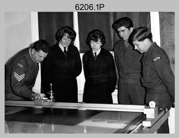
Photograph - Co-ordinatorgraph Map Grid Production, Army Survey Regiment, Fortuna Bendigo, c1960s to 1970s
... aerial triangulated stereo model control. This could be used for a number of maps and was the first step towards map automation. The history of co-ordinatorgraphs is covered in more detail with additional historic photographs, in pages 50 to 51 and page 88 of Valerie Lovejoy’s book 'Mapmakers of Fortuna – A history of the Army Survey Regiment’ ISBN: 0-646-42120-4. SGT Bill Boyd appearing in photo .1P reach the rank of WO1 and for 11 years was the technical warrant officer at the Detachment Army Survey Regiment located at Bonegilla, Victoria...aerial triangulated stereo model control. This could be used for a number of maps and was the first step towards map automation. The history of co-ordinatorgraphs is covered in more detail with additional historic photographs, in pages 50 to 51 and page 88 of Valerie Lovejoy’s book 'Mapmakers of Fortuna – A history of the Army Survey Regiment’ ISBN: 0-646-42120-4. SGT Bill Boyd appearing in photo .1P reach the rank of WO1 and for 11 years was the technical warrant officer at the Detachment Army Survey Regiment located at Bonegilla, Victoria ...This is a set of seven photographs of map grid production using co-ordinatorgraphs at the Army Survey Regiment, Fortuna Bendigo. c1960s to 1970s. The Aristo Co-ordinatorgraph introduced in 1962 was a large heavy steel framed light table with a scribing head that moved in a XY direction using a vernier calibrated measuring scale to 0.001 of an inch. Whilst hand operated it was much quicker and accurate than manual grid and graticule calculation, plotting and scribing. Mapping PNG presented the Regiment with many challenges. WO1 Farrington and CPL John Dean developed computer software for the digitally controlled co-ordinatorgraph, the Calcomp 718 Flatbed Plotter. Much time was saved by automatically plotted cartographic grids and graticules, and automatically draw base compilation sheets complete with aerial triangulated stereo model control. This could be used for a number of maps and was the first step towards map automation. The history of co-ordinatorgraphs is covered in more detail with additional historic photographs, in pages 50 to 51 and page 88 of Valerie Lovejoy’s book 'Mapmakers of Fortuna – A history of the Army Survey Regiment’ ISBN: 0-646-42120-4. SGT Bill Boyd appearing in photo .1P reach the rank of WO1 and for 11 years was the technical warrant officer at the Detachment Army Survey Regiment located at Bonegilla, Victoria. He was awarded the OAM, the Order of Australia Medal for the development of the Flexiflow quality control system. This system comprised a series of job plans and charts linked to a task allocation to resource magnetic planning board. Using critical path analysis and task prioritisation, complex job planning was efficiently scheduled, and re-prioritisations readily made. Reproduction requirements were effectively coordinated by way of weekly courier to the Army Survey Regiment. Supervisors and technicians fully embraced the system as they could understand their role, others around them and the positive production achievements. Bendigo. See page 178 of Valerie Lovejoy’s book for more information on WO1 Boyd’s contribution to RA Svy.This is a set of seven photographs of map grid production using co-ordinatorgraphs at the Army Survey Regiment, Fortuna Bendigo. c1960s to 1970s. The photographs were printed on photographic paper and are part of the Army Survey Regiment’s Collection. The photographs were scanned at 300 dpi. .1) - Photo, black & white, c1960s, L to R: SGT Bill Boyd demonstrating Aristo Co-ordinatorgraph equipment to unidentified technicians (x3) .2) - Photo, black & white, c1960s, Aristo Co-ordinatorgraph equipment. .3) - Photo, black & white, c1960s, unidentified technician operating Aristo Co-ordinatorgraph equipment. .4) - Photo, black & white, c1960s, L to R: PTE Desi Asaris and CPL Kalen Sargent operating Aristo Co-ordinatorgraph equipment. .5) - Photo, black & white, Photo, black & white, c1970s, John Bloor operating Calcomp co-ordinatorgraph equipment. .6) - Photo, black & white, Photo, black & white, c1970s, unidentified technician operating Calcomp co-ordinatorgraph equipment. .7) - Photo, black & white, Photo, black & white, c1970s, L to R: SGT Andy Covington and SGT John Waight operating Calcomp co-ordinatorgraph equipment..7P annotated on back ‘Covington & Waight’.royal australian survey corps, rasvy, army survey regiment, army svy regt, fortuna, asr, carto, air survey -
 Bendigo Military Museum
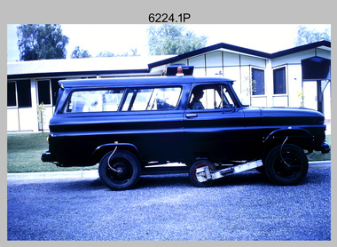
Photograph - Johnson Ground Elevation Meter (JGEM) Survey Vehicle - Army Survey Regiment, Fortuna, Bendigo, c1960s
... aerial photographs. Under favourable conditions it was possible to survey as much as 160km in an ordinary working day. The first of RA Svy’s JGEM operations was undertaken in 1:250,000 scale map areas of Queensland. CPL John Hook was the JGEM’s main operator in the early 1970s undertaking operations covering 1:250,000 scale map blocks over northern Victoria and central NSW, each requiring 36 points (9 runs of photography and 4 points across. ...aerial photographs. Under favourable conditions it was possible to survey as much as 160km in an ordinary working day. The first of RA Svy’s JGEM operations was undertaken in 1:250,000 scale map areas of Queensland. CPL John Hook was the JGEM’s main operator in the early 1970s undertaking operations covering 1:250,000 scale map blocks over northern Victoria and central NSW, each requiring 36 points (9 runs of photography and 4 points across. ...This is a set of 16 photograph of the Royal Australian Survey Corps’ Johnson Ground Elevation Meter (JGEM) Survey Vehicle taken at the Army Survey Regiment, Fortuna, Bendigo. The JGEM vehicle was extensively used by RA Svy within Australia from the late 1960s. A limited number of Ground Elevation Meter (GEM) station wagon type vehicles were manufactured by General Motors Corporation (GMC) in the USA for the United States Geological Survey, Canada’s mapping agencies, RA Svy and National Mapping (Natmap). The GEM was a four-wheel drive, four-wheel steer vehicle. Four-wheel steering was necessary to avoid systematic errors caused by non-tracking of front and rear wheels on conventionally steered vehicles. The manufacturer substituted the rear axle with a front axle and connected them to form the four-wheel steering mechanism. The two Australian GEM vehicles, referred to as Johnson GEMs (JGEMs) were converted into right-hand drive. After delivery in 1964, acceptance Natmap and RA Svy testing and operator training was undertaken at the Army's School of Military Survey located at Balcombe, Victoria. A small fifth wheel was mounted on a cantilever arm suspension midway between the front and rear wheels on the right side of the vehicle. It was lowered to and raised from its operating position by use of a constant pressure air cylinder. A telescopic bar, suspended between the front and rear axles, provided the reference datum for the angle measurement. The wheel provided the velocity or distance signal through a pulse generator system. A sensitive pendulum mounted on this bar provided the angle measurement for each minute distance traversed. The JGEM contained electromechanical instruments used to determine relative elevations, by trigonometric principles, along a traversed path. These relative elevations were obtained through apparatus which measures the instantaneous angle of inclination of the road and the instantaneous velocity of the meter along such a path. Road routes over which the JGEM operated were planned so that each started and ended as near as practicable to an existing point of known elevation (formally referred to as a level traverse bench mark). The difference in height from the bench mark and the road surface alongside the JGEM’s fifth wheel was measured with a level and staff. Along each route, mapping control photo reference points where new elevation values were required were identified on aerial photographs. Under favourable conditions it was possible to survey as much as 160km in an ordinary working day. The first of RA Svy’s JGEM operations was undertaken in 1:250,000 scale map areas of Queensland. CPL John Hook was the JGEM’s main operator in the early 1970s undertaking operations covering 1:250,000 scale map blocks over northern Victoria and central NSW, each requiring 36 points (9 runs of photography and 4 points across. SPR Lyn Thompson and SPR Bob McDonagh teamed with CPL Hook on some of these JGEM operations. When RA Svy was integrated into the Royal Australian Engineers in 1996, the JGEM vehicle with the Survey Corps collection was donated to its museum. It is believed to be the last of the original manufactured fleet in existence. The JGEM has undergone extensive refurbishment to achieve roadworthiness and is currently housed at The Australian Army Museum of Military Engineering, Hoslworthy Barracks, NSW. It can be viewed by making an appointment with the museum’s curator.This is a set of 16 photograph of the Royal Australian Survey Corps’ Johnson Ground Elevation Meter (JGEM) Survey Vehicle taken at the Army Survey Regiment, Fortuna, Bendigo. The photographs were on 35mm slide film and were scanned at 96 dpi. They are part of the Army Survey Regiment’s Collection. .1) - Photo, colour, c1960s, Johnson Ground Elevation Meter (JGEM) Survey Vehicle .2) - Photo, colour, c1960s, JGEM instrumentation, on-board computer. .3) - Photo, colour, c1960s, JGEM instrumentation. .4) - Photo, colour, c1960s, JGEM instrumentation, on-board computer. .5) - Photo, colour, c1960s, JGEM tyre pressure controller .6) - Photo, colour, c1960s, JGEM rear doors, SGT Geoff Briggs. .7) - Photo, colour, c1960s, JGEM 5th wheel distance/angle measurement device in lowered position, SGT Geoff Briggs. .8) - Photo, colour, c1960s, JGEM 5th wheel distance/angle measurement device in lowered position. .9) & .10) - Photo, colour, c1960s, JGEM tyre pressure system, SGT Geoff Briggs. .11) - Photo, colour, c1960s, JGEM tyre pressure system. SGT Geoff Briggs. .12) - Photo, colour, c1960s, JGEM levelling scope, levelling staff, unidentified technicians. .13) & .14) - Photo, colour, c1960s, JGEM levelling scope, unidentified technician. .15) & .16) - Photo, colour, c1960s, probably survey operation adjusted height plotted on block base sheet. .1P to .16P - Some of the equipment is annotated on the frame of the 35mm slides.royal australian survey corps, rasvy, army survey regiment, army svy regt, fortuna, asr, surveying -
 Emerald Museum & Nobelius Heritage Park
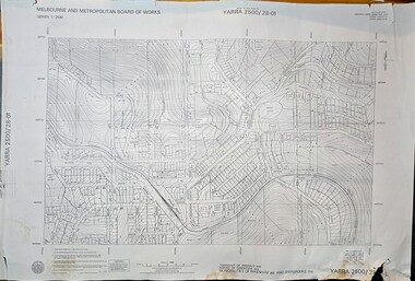
Map - Melbourne & Metropolitan Board of Works, Emerald Victoria, Topographical Map - Amendment 16.1.89, Melbourne and Metropolitan Board of Works, MMBW Topographical Map -Yarra 2500/28.01, 1989
... Aerial Mapping (Vic.) Pty.Ltd. Date of Photography: January 1981/Base prepared by the Survey Division, Melbourne and Metropolitan Board of Works, under the direction of K.A. Mitchell, Chief Surveyor, Engineering Branch: May 1984/Survey Co-ordination Act plan classification BB2/Revised and re-issued/Latest cadastral amendment 16.1.89/Scale 1:2500/Township of Emerald 5280, Parish of Gembrook 2645, Municipalities of Pakenham 262 And Sherbrooke259/YARRA 2500/28.01 Image of printed Melbourne & Metropolitan Board of Works topographical map - Emerald - Yarra 2500/28.01 MMBW Topographical Map -Yarra 2500/28.01 Map Melbourne & Metropolitan Board of Works, Emerald Victoria, Topographical Map - Amendment 16.1.89 Melbourne and Metropolitan Board of Works ...Topographical map of Emerald township from 1989, based on photography from 1981Image of printed Melbourne & Metropolitan Board of Works topographical map - Emerald - Yarra 2500/28.01non-fictionTopographical map of Emerald township from 1989, based on photography from 1981emerald -
 Emerald Museum & Nobelius Heritage Park
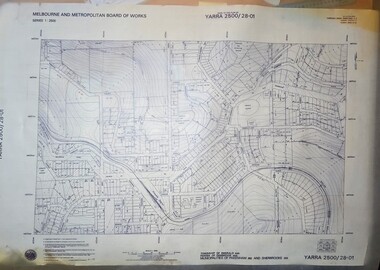
Map - Transparency edition - Melbourne & Metropolitan Board of Works, Emerald Victoria, Topographical Map - Amendment 16.1.89, Melbourne and Metropolitan Board of Works, MMBW Topographical Map -Yarra 2500/28.01, 1989
... Aerial Mapping (Vic.) Pty.Ltd. Date of Photography: January 1981/Base prepared by the Survey Division, Melbourne and Metropolitan Board of Works, under the direction of K.A. Mitchell, Chief Surveyor, Engineering Branch: May 1984/Survey Co-ordination Act plan classification BB2/Revised and re-issued/Latest cadastral amendment 16.1.89/Scale 1:2500/Township of Emerald 5280, Parish of Gembrook 2645, Municipalities of Pakenham 262 And Sherbrooke259/YARRA 2500/28.01 Image of printed Melbourne & Metropolitan Board of Works topographical map - Emerald - Yarra 2500/28.01 MMBW Topographical Map -Yarra 2500/28.01 Map Transparency edition - Melbourne & Metropolitan Board of Works, Emerald Victoria, Topographical Map - Amendment 16.1.89 Melbourne and Metropolitan Board of Works ...Topographical map of Emerald township from 1988Image of printed Melbourne & Metropolitan Board of Works topographical map - Emerald - Yarra 2500/28.01non-fictionTopographical map of Emerald township from 1988emerald -
 Emerald Museum & Nobelius Heritage Park
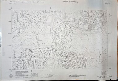
Map - Melbourne & Metropolitan Board of Works, Emerald Victoria, Topographical Map - Amendment 5.1.88, Melbourne and Metropolitan Board of Works, MMBW Topographical Map -Yarra 2500/29.01, 1988
... Aerial Mapping (Vic.) Pty.Ltd. Date of Photography: January 1984/Base prepared by the Survey Division, Melbourne and Metropolitan Board of Works, under the direction of B.K. Marwick, Chief Surveyor, Engineering Branch: May 1986/Survey Co-ordination Act plan classification BB2/Revised and re-issued/Latest cadastral amendment 15.1.88/Scale 1:2500/Parish of Gembrook 2645, Municipalities of Pakenham 262 And Sherbrooke259/YARRA 2500/29.01 Image of printed Melbourne & Metropolitan Board of Works topographical map - Emerald - Yarra 2500/29.01 MMBW Topographical Map -Yarra 2500/29.01 Map Melbourne & Metropolitan Board of Works, Emerald Victoria, Topographical Map - Amendment 5.1.88 Melbourne and Metropolitan Board of Works ...Topographical map of Emerald township from 1989, based on photography from 1981Image of printed Melbourne & Metropolitan Board of Works topographical map - Emerald - Yarra 2500/29.01non-fictionTopographical map of Emerald township from 1989, based on photography from 1981emerald -
 Emerald Museum & Nobelius Heritage Park
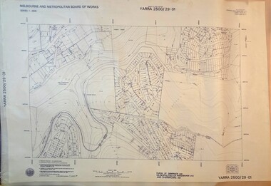
Map - Transparency of Melbourne & Metropolitan Board of Works, Emerald Victoria, Topographical Map - Amendment 5.1.88, Melbourne and Metropolitan Board of Works, MMBW Topographical Map -Yarra 2500/29.01, 1988
... Aerial Mapping (Vic.) Pty.Ltd. Date of Photography: January 1984/Base prepared by the Survey Division, Melbourne and Metropolitan Board of Works, under the direction of B.K. Marwick, Chief Surveyor, Engineering Branch: May 1986/Survey Co-ordination Act plan classification BB2/Revised and re-issued/Latest cadastral amendment 15.1.88/Scale 1:2500/Parish of Gembrook 2645, Municipalities of Pakenham 262 And Sherbrooke259/YARRA 2500/29.01 Image transparency of printed Melbourne & Metropolitan Board of Works topographical map - Emerald - Yarra 2500/29.01 MMBW Topographical Map -Yarra 2500/29.01 Map Transparency of Melbourne & Metropolitan Board of Works, Emerald Victoria, Topographical Map - Amendment 5.1.88 Melbourne and Metropolitan Board of Works ...Topographical map of Emerald township from 1988Image transparency of printed Melbourne & Metropolitan Board of Works topographical map - Emerald - Yarra 2500/29.01non-fictionTopographical map of Emerald township from 1988emerald -
 Bendigo Military Museum
Photograph - Multiplex mechanical stereoplotting equipment, Army Survey Regiment, Fortuna Bendigo, c1950s
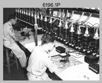
... aerial photography, however was restricted to each strip rather than between strips in the block. Although the Multiplex was phased out of production in 1968, it was used in the training of photogrammetry and aero-triangulation at the School of Military Survey located at Bonegilla, Victoria until the early 1990s. ...aerial photography, however was restricted to each strip rather than between strips in the block. Although the Multiplex was phased out of production in 1968, it was used in the training of photogrammetry and aero-triangulation at the School of Military Survey located at Bonegilla, Victoria until the early 1990s. ...This is a set of five photographs of Multiplex mechanical stereoplotting equipment at the Army Survey Regiment, Fortuna Bendigo. c1950s. Multiplex equipment was imported from the UK in 1951 and introduced in the following year, to accelerate map production output covering CMF training areas at 1:25,000 map scale. Multiplex plotting was a productive advancement replacing the ‘Arundel’ method of graphical plotting planimetric detail that was expensive and slow, especially in timbered mountainous terrain. Air photos were made into small diapositives and mounted on racks in the exact position relative to when the aerial photos were taken. The technicians operated the Multiplex in a darkened room, with one photo projected with a green filter and the other through a red filter to form a 3D view of the overlapping photos. The 3D model projected onto a platen, which was a small platform that was raised up and down. The technician viewed the 3D image with special glasses fitted with red and green lenses. In the centre of the platen was a small pinhole that served as a floating mark, with a vertical pencil located exactly below the pinhole. This tracing table was moved to follow the topographic feature or contour line and draw it on the paper underneath. The technician raising or lowering the platform’s floating mark to match the height of the 3D terrain. It also replaced the slotted template method of mechanical adjustment of strips of aerial photography, however was restricted to each strip rather than between strips in the block. Although the Multiplex was phased out of production in 1968, it was used in the training of photogrammetry and aero-triangulation at the School of Military Survey located at Bonegilla, Victoria until the early 1990s. The history of the Multiplex is covered in more detail with additional historic photographs, in pages 50 to 51 of Valerie Lovejoy’s book 'Mapmakers of Fortuna – A history of the Army Survey Regiment’ ISBN: 0-646-42120-4.This is a set of five photographs of Multiplex mechanical stereoplotting equipment at the Army Survey Regiment, Fortuna, Bendigo. c1950s. The photographs were printed on photographic paper and are part of the Army Survey Regiment’s Collection. The photographs were scanned at 300 dpi. .1) - Photo, black & white, c1950s, unidentified personnel operating Multiplex equipment. .2) - Photo, black & white, c1950s, Multiplex equipment. .3) - Photo, black & white, c1950s, Multiplex components identified. .4) - Photo, black & white, c1950s, Multiplex optical components. .5) - Photo, black & white, c1950s. Unidentified technician laying down individual Multiplex plots..1P to .2P, .4P – No annotations. .3P annotations identifying Multiplex components on front of photo. .5P annotated on front ‘Lay down of individual Multiplex plots at 1/14000 to framework of master grid to form Composite Compilation Sheet – Material Duralex.’royal australian survey corps, rasvy, army survey regiment, army svy regt, fortuna, asr, photogrammetry -
 Bendigo Historical Society Inc.
Photograph - Aerial photographs of parts of Bendigo 1934, 1934
... Clive Willman Senior Geologist Geological Survey of Victoria AERIAL SHOTS OF PARTS OF BENDIGO 1934 Catalogue No.10584 This document contains scans of a unique set of aerial photographs that were taken over the City of Bendigo on Friday 12th January 1934, at about midday. ...AERIAL SHOTS OF PARTS OF BENDIGO 1934 Catalogue No.10584 This document contains scans of a unique set of aerial photographs that were taken over the City of Bendigo on Friday 12th January 1934, at about midday. The photographs were commissioned by Bendigo Mines Limited during their exploration and mining program designed to revitalize the Bendigo Goldfield. The photographs were given to the Victorian Mines Department sometime in the 1950s. The photographs were taken at a relatively low level of about 4000 feet. This gives a very detailed picture of Bendigo as it was in the 1930s. The photos cover the City Centre and are mainly of the goldfields on the south side of the city; the extent of which covers approximately the four corners of Myers Flat, Maiden Gully, Mandurang and One Tree Hill. Streets, roads and places of interest have been identified as best as possible in December 2023. There are 44 maps, and each references the adjoining maps.Typed Notes with CD The CD is one of two and contains a set of 46 images: The folder named "High_Resolution_800dpi" contains the original digital files that were produced by scanning the photographic prints (About A3 size) at 800 dpi using a high quality, large pformat, roll scanner. These files may be too large for some computers. A second CD contains a direstory called "Low_Resolution_300dep" The images in the folder names "Low_Reolution_300dpr" have a lower resolution (300 dpi) and have been rotated 90 degrees clockwise so that the Northern margin of each image is a the top of the screen. Clive Willman Senior Geologist Geological Survey of Victoriahistory, bendigo, bendigo mines, bendigo maps, bendigo aerial photos -
 Bendigo Military Museum
Instrument - Old Delft Scanning Stereoscope ODSS III, C. 1956
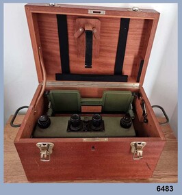
... aerial photographs. In the public and private sector it was also useful for photogrammetric interpretation for Forestry and Agricultural purposes. See also Bendigo RSL Collections Victoria item Number 6205.6P that shows the Old Deft Stereoscope in use at the Army Survey Regiment, Bendigo....aerial photographs. In the public and private sector it was also useful for photogrammetric interpretation for Forestry and Agricultural purposes. See also Bendigo RSL Collections Victoria item Number 6205.6P that shows the Old Deft Stereoscope in use at the Army Survey Regiment, Bendigo. ...This is a superbly crafted cartographic mapping instrument. It is housed in its own high-quality purpose-built oak box. Made in the Netherlands from 1950 onwards. This instrument is from c 1956. it is a very high-quality military grade stereoscope that was generally used by photographic interpreters such as intelligence analysts but was equally useful for mapping activities. The stereoscope was used to examine 3D aerial photographic images. This instrument has a particularly useful capability to scan over the 3D stereo model using X and Y movement knobs, rather than having to physically move the aerial photographs. In the public and private sector it was also useful for photogrammetric interpretation for Forestry and Agricultural purposes. See also Bendigo RSL Collections Victoria item Number 6205.6P that shows the Old Deft Stereoscope in use at the Army Survey Regiment, Bendigo.This is an "Old Delft" scanning stereoscope with its reflecting carriage and legs. The Stereoscope is housed in its own purpose built wooden oak box that has dovetail joints, 2 x securing clips, 2 x handles and a lock (without key). The instrument is assembled by inserting colour coded legs into their matching slots."OLD DELFT SCANNING STEREOSCOPE ODSS III" "Patents Applied for" "OLD DELFT C4790" "MADE IN THE NETHERLANDS"royal australian survey corps, rasvy, fortuna, army survey regiment, army svy regt, asr -
 Bendigo Military Museum
Photograph - 4th Field Survey Squadron – Operation NERVOSE 85 Field Phase Oblique Photos, NT, 1985
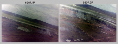
... This is a set of 20 oblique aerial photographs taken during the field phase of 4th Field Survey Squadron’s Operation NERVOSE 85 project in the Northern Territory in 1985. Operation NERVOSE 85 was mounted by 4 Fd Svy Sqn in the EAST ARNHEM, VICTORIA RIVER DOWNS AND DALY WATERS areas of the Northern Territory from 26 May to 18 Sep 85. ...Royal Australian Survey Corps RASvy 4 Fd Svy Sqn OP NERVOSE 85 .1P to .20P – There are no personnel identified. ‘1987 OP NERVOSE VICTORIA RIVER DOWNS AND DALY WATERS.’ annotated on negative sleeve. This is a set of 20 oblique aerial ...This is a set of 20 oblique aerial photographs taken during the field phase of 4th Field Survey Squadron’s Operation NERVOSE 85 project in the Northern Territory in 1985. Operation NERVOSE 85 was mounted by 4 Fd Svy Sqn in the EAST ARNHEM, VICTORIA RIVER DOWNS AND DALY WATERS areas of the Northern Territory from 26 May to 18 Sep 85. The aim of Operation NERVOSE 85 was to finalise the horizontal and vertical control for mapping at a scale of 1:50,000, to field check 40x 1:50,000 preliminary maps and to obtain mapping photography in support of the RAAF TINDAL redevelopment project. *Note –These photos were most likely taken in 1985, contrary to the ‘1987’ date annotated on the negative sleeves. The Op NERVOSE 85 Project Report available on RASVY’s web site lists a nominal roll of personnel. Photos of 4 Fd Svy Sqn taken in 1985 and 1987 provide names of posted personnel. Several personnel identified in these photos were posted to 4 Fd Svy Sqn in 1985, not in 1987. See items 6504.13P, 6505.28P and 6506.16P for more photos taken prior to and during Operation NERVOSE 1985. This is a set of 20 oblique aerial photographs taken during the field phase of 4th Field Survey Squadron’s Operation NERVOSE 85 project in the Northern Territory in 1985. The colour photographs on 35mm negative film and are part of the Army Survey Regiment’s Collection. The photographs were scanned at 96 dpi. .1) to .20) - Photo, colour, 1985. Unknown locations..1P to .20P – There are no personnel identified. ‘1987 OP NERVOSE VICTORIA RIVER DOWNS AND DALY WATERS.’ annotated on negative sleeve.royal australian survey corps, rasvy, 4 fd svy sqn, op nervose 85 -
 Bendigo Military Museum
Administrative record - Australian Survey Corps - Liaison Letters 1936 - 1939, 1st, 2nd, 3rd and 4th Military Districts, Australia, July 1936 - June 1939
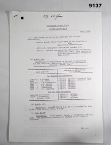
... Aerial Surveying. -- Article missing. .... W/O H. A. Johnson. -- A type of Beacon. -- Article missing. Para 2. Progress of work. ..... No1 Draughting Section. ..... No1 Survey Section. ..... Pages missing. 9137.5 Liaison Letter No 5, July 1937. Para 1. Our thanks are due to the following for articles contributed .... Lt L. Fitzgerald -- A new section and its job. -- Article missing. .... WO G.R.L. Remington. .... & H. E. Eggeling. Azimuth of the Plane table. -- Article missing. .... W.O. B. M. Sarll. -- The Second Annual Smoke Night of the Members of the Aust.Survey Corps stationed in Victoria...Aerial Surveying. -- Article missing. .... W/O H. A. Johnson. -- A type of Beacon. -- Article missing. Para 2. Progress of work. ..... No1 Draughting Section. ..... No1 Survey Section. ..... Pages missing. 9137.5 Liaison Letter No 5, July 1937. Para 1. Our thanks are due to the following for articles contributed .... Lt L. Fitzgerald -- A new section and its job. -- Article missing. .... WO G.R.L. Remington. .... & H. E. Eggeling. Azimuth of the Plane table. -- Article missing. .... W.O. B. M. Sarll. -- The Second Annual Smoke Night of the Members of the Aust.Survey Corps stationed in Victoria ...Liaison Letters details happenings within the various Sections of the Australian Survey Corps to inform all members of current information and practices. 9137.1 Liaison Letter No 1. 21 July 1937. Para 1. Object of Letter. See context section. Para 3. Progress of work. Incomplete, rest of Letter missing only 1 page. 9137.2 Liaison Letter No 2 Letter missing. 9137.3 Liaison Letter No 3. Jan 1937. Para 1. Our thanks are due to the following for articles contributed. .... W/O H. Rossiter. -- "Aerial Surveying". -- Article missing. .... W/O W. M. Sarll. -- "A day in the Draughting Office". -- Report on No 1 Field Sheet, Sale. -- Article missing. .... W/O H. A. Johnson. -- "Semigraphic methods of resection and intersection". -- Article missing. .... Capt. J.J. Raisbeck "Rapid production and reproduction of Military maps". Article missing. .... Lt. L. Fitzgerald. report "Survey Exercise at Sale". Article missing. .... W/O W. M. Sarll. report on No1. Field Sheet, Sale. Article missing. Para 3. Progress of work. .... "No1 Draughting Section". .... Printing. .... No1 Survey Section. .... No2 Survey Section. .... Pages 3 - 6 Missing. .... Article by W/O W. M. Sarll. "A day in the Draughting Office". Pages 7 - 10. 9137.4 Liaison Letter No 4. April 1937. Para 1. Our thanks are due to the following for articles contributed. .... Lieut. H. W. G. Clews. -- Notes on the non-ascertained Base problem. -- Article missing. .... W/O W. M. Sarll. -- Helpful hints on air photos. -- Article missing. .... Capt. T. H. B. Foott. .... & Capt. J.J. Raisbeck. -- A short history of the Military Survey of Australia. -- Article missing. .... W/O H. Rossiter. -- Notes on Aerial Surveying. -- Article missing. .... W/O H. A. Johnson. -- A type of Beacon. -- Article missing. Para 2. Progress of work. ..... No1 Draughting Section. ..... No1 Survey Section. ..... Pages missing. 9137.5 Liaison Letter No 5, July 1937. Para 1. Our thanks are due to the following for articles contributed .... Lt L. Fitzgerald -- A new section and its job. -- Article missing. .... WO G.R.L. Remington. .... & H. E. Eggeling. Azimuth of the Plane table. -- Article missing. .... W.O. B. M. Sarll. -- The Second Annual Smoke Night of the Members of the Aust.Survey Corps stationed in Victoria. .... Also included is a very interesting article on the United States Geological Survey by J. F. Staask, extracted from the Canadian Surveyor. February 1936. -- Article missing. Para 2. Progress of work. .... No1. Draughting Section. .... No 1 Topographical Section. No further articles till page 7. .... The Second Annual Smoke Night of the members of the Aust. Survey Corps. Stationed in Victoria. Pages 7 - 9. 9137.6 Liaison Letter No 6, September 1937. Para 1. Our thanks are due to the following for articles contributed .... Lt L. Fitzgerald. -- Geodetic Triangulation reconnaissance. Article missing. -- Article missing. .... Lt. R.F. Rule, M.M. -- A suggested Form for Field Book 3rd Order Traverses. -- Article missing. .... W/O. H. A. Johnson. -- A suggested Form for Quadrilateral Adjustments. -- Article missing. Para 2. Progress of work. .... No1. Draughting Section. .... No 1 Topographical Section. No further pages to letter 6. 9137.7 Liaison Letter No 7. January 1938. Para 1. Our thanks are due to the following for articles contributed. .... Major T. A. Vance. -- Report on the Survey of a Training Area in Tasmania. -- Article missing. .... W/O D. Macdonald. -- The naming of Trigonometrical Stations. -- Article missing. Para 2. Progress of work. .... No1 Draughting Section A.H.Q. .... No1 Topographical Section, 4 M.D. .... No2 Topographical Section 3 M.D. .... No3 Topographical Section 2 M.D. .... No4 Topographical Section A.H.Q. No further pages to letter 7. 9137.8 Liaison Letter No 8. April 1938. Para 1. Our thanks are due to the following for articles contributed .... Capt. H.P.G.Clews. -- A possible method of estimating Stereoscopic ability. -- Article missing. .... W/O. A.L.Smith. -- Hints to Topographers from a Draughtsman's point of view. .... W/O. W.W. Sarll. -- Seeing that which a Surveyor sees. Para 1.a. -- Relative to article on naming of trig stations which appeared in No7. This contribution has examples of naming. Para 1.d. Enlistment. -- George Gladstone Bolwell was enlisted as W/O.II. Draughtsman in the No. 1 Draughting Section A.H.Q. on the 26th April 1938. Mr. Bolwell was of the Victorian Lands Department. Para 1.e. Embarkation. -- Major T.A. Vance. O.C. Aust Survey Corps, embarked S.S. "Monterey". 28 Mar 1938 to undergo six months training in USA and Canada. Para 1.f. Promotions. -- To be Capt. (prov.) Lieut. H.P.G. Clews 9.11.1937. Para 1.g. Medals -- Award of Aust. Meritorious Service Medal -- W/O.H. Rossiter. .... Award of Aust. Medal for Long Service and Good Conduct -- W/O, A.L. Smith. Para 2. Progress of work. .... No.1 Draughting Section A.H.Q. .... No.1 Topographical Section, 4 M.D. .... No.2 Topographical Section 3 M.D. .... No.3 Topographical Section 2 M.D. .... No.4 Topographical Section A.H.Q. Article missing by Capt. H.P.G.Clews. -- A possible method of estimating Stereoscopic ability. Article by W/O. A.L.Smith. -- Hints to Topographers from a Draughtsman's point of view. Contains 3 pages. Article by W/O. W.W. Sarll. -- Seeing that which a Surveyor sees. Contains 3 pages. 9137.9 Liaison Letter No 9. July 1938. Para 1. Our thanks are due to the following for articles contributed .... Captain H.P.G.Clews -- Computation of log p and log v; also Abbreviated interpolation. .... W/O. G.R.L. Rimington. -- Light Weight Camping Gear. .... W/O. H.A. Johnson. -- The use of the Calculating Machine on Resections, etc,; also comments by O.C.No.4 Topographical Section on this article. Para 1.a. A.A.O. 104. Examination for Appointment to the Rank of Lieutenant. February - March,1938. .... W.O.I. A.L. Smith. .... W.O.I. W.M. Sarll. .... W/O. II. G.R.L. Rimington. .... W/O. II. A.F. Kurrle. .... W/O. II. H.A. Johnson. .... W/O. II. D. MacDonald. .... W/O. II. H.F.Eggeling. .... For Captain. .... Capt. (p) H.P.G. Clews. .... Lieut. L. FitzGerald. .... Lieut. R.K. Rule M.M. Para.1. b. A.A.O. 109. Allotment W/O. II. W.B. Relf to No.3 Topo Section 2 M.D., 5.4.38. Para.1. c. Gaz. No. 37 -- Promotions. -- To be Captain, Lieut. L FitzGerald. 5th July 1938. -- The provisional promotion of Captain H.P.G. Clews is confirmed. Para. 2. Progress of Work. .... No.1 Draughting Section A.H.Q. .... No.1 Topographical Section, 4 M.D. .... No.2 Topographical Section 3 M.D. .... No.3 Topographical Section 2 M.D. .... No.4 Topographical Section 2 M.D. 9137.10 Liaison Letter No 10. October 1938. Para 1. Our thanks are due to the following for articles contributed. .... Lieut. R.K. Rule M.M. -- Barometric levelling in Forest Areas. .... W/O. H.A. Roseblade -- Adjustment of principal points on master grid. .... W/O. II. A.F. Kurrle. -- The Hunter short base applied to photo control. .... W/O. W.B. Relf -- Reunion at Newcastle. .... The articles are all missing Para. 1. a. A.A.O. 184. Discharge -- W/O. II. G.G. Bolwell. 15th July 1938. Para. 1. b. A.A.O. 174-195, 31.8.38. Vacancy for Draughtsman. Para. 1. c. Obituary. -- Major John Lynch. 29th July 1938. Para. 2. Progress of Work. .... No.1 Draughting Section A.H.Q. .... No.1 Topographical Section, 4 M.D. .... No.2 Topographical Section 3 M.D. .... No.3 Topographical Section 2 M.D. .... No.4 Topographical Section A.H.Q. 9137.11 Liaison Letter No 11. January 1939. Para 1. Our thanks are due to the following for articles contributed. .... Major T.A. Vance. -- Training Abroad, Canada and U.S.A. .... Captain L. Fitzgerald -- Air Reconnaissance for 1st Order Triangulation. .... W/O C.E. Stewart. -- Reunion at Traralgon. Para 2. A.A.O. 301/38. .... a. Appointments. -- Royal Ormond Worcester, on enlistment in the Aust Permanent Military Forces is appointed W/O II. 30th November 1938. -- Thomas Micheal Connolly, on enlistment in the Aust Permanent Military Forces is appointed W/O II. 30th November 1938. .... b. Discharge. -- No. 3614 W/O II. G.R.L. Rimington. 30th November 1938. .... c. Awards of the Australian Military Medal for Long Service and Good Conduct (Military). -- No.1175, W/O I, E.T. Johnson. .... d. Return of Officers to Australia. -- Major T.A. Vance, having completed training in the United States of America, Canada and New Zealand, returned to Aust. on the S.S. "Awatea", disembarked Sydney on 3rd December 1938. .... e. Allotment. -- No.3689, W/O. II A.F. Kurrle, allotted to No. 4 Topographical Section, A.H.Q., 1 January 1939. Para. 2. Progress of Work. .... Cartographic Section, A.H.Q. .... Geodetic Section, A.H.Q. .... No.1 Survey Section, 4 M.D. .... No. 2 Survey Section, 3 M.D. .... No. 3 Survey Section, 2 M.D. 9137.12 Liaison Letter No 12. March 1939. Para 1. Our thanks are due to the following for articles contributed. .... W/O H.F. Eggeling -- Topographical Survey and Barometric Levelling. .... W/O G.T.P. Carter Methods of plotting from air photographs. .... Editor, Canadian Surveyor -- The Australian Survey Corps Para 2. A.A.O. 57 -- .... a. Promotion. -- No. 3577 S/Sgt G.T.P. Carter. appointed Topographer promoted to W/O II. 15th January 1939. .... b. Allotment -- The following are allotted to No. 3 Topographical Section 2 M.D. 1st February 1939. .... No, 171 W/O I B. Rossiter. .... No. 178 W/O. I V.W. Aldred. .... No. 150 W/O. I A.T. Smith. .... c. Transfer. -- No. 369 W.O. A.F.Kurrle. to No. 4 Topo Section A.H.Q. 1st January 1939. .... d. Promotions -- To be Major J.J. Raisbeck. and Lieut. W.M. Sarll as of 1st January 1939. Para. 3. Progress of Work. .... Cartographic Section, A.H.Q. .... No.4 Topographical Section, A.H.Q. .... No.2 Topographical Section, 3 M.D. .... No.3 Topographical Section, 2 M.D. .... Articles Missing -- W/O H.F. Eggeling -- Topographical Survey and Barometric Levelling. -- W/O G.T.P. Carter Methods of plotting from air photographs .... Article -- Editor, Extract from "The Canadian Surveyor" -- The Australian Survey Corps. 9137.13 Liaison Letter No 13. June 1939. Para 1. Our thanks are due to the following for articles contributed. .... Lieut. W.M. Sarll -- Meeting a crisis with maps and equipment; also comments by O.C. Cartographic Section. .... W/O H.F. Eggeling -- Design and description of an Epidiascope. -- Article missing. .... Editor, Melbourne Herald -- "They do a Vital Task". 6th July, 1939. .... Also enclosed is a Corps Seniority Roll. -- Article missing. Para 2. a. A.A.O. 118/39. -- Appointment to Lieutenant, February, March, 1939. .... 3572 W/O. I. H.C. Raisbeck. .... 3684 W/O. I.I. T.R. Westgarth. .... 3686 W/O. I.I. C.E.B. Stewart. .... 3702 W/O. I.I. C. S. Tyler. .... 4479 W/O. I.I. W.B. Relf. Para. 2. b. A.A.O. 127/39 -- Appointment to W/O. I.I. .... G. V. Brooke. 5.4.39. .... L. J. Lockwood. 5.4.39. .... J. P. Hanley. 17.4.39. .... W. J. Harrison. 24.4.39. .... J. K. C. Herridge. 1.5.39. Para 2. c Gaz. 26/39. Awards of the Aust. Medal for Long Service and Good Conduct Military. .... No. 1439 W/O. I. H. A. Roseblade. .... No. 1176 W/O. I. J. Cullen. Para. 3. Progress of Work. .... Cartographic Section, A.H.Q. .... Geodetic Section A.H.Q. .... No. 2 Survey Section, 3 M.D. .... No. 3 Survey Section, 2 M.D. .... Editor, Melbourne Herald -- "They do a Vital Task". 6th July, 1939. .... Lieut. W.M. Sarll -- Meeting a crisis with maps and equipment; also comments by O.C. Cartographic Section. 9137.1 Liaison Letter No 1. 21 July 1937. Para 1. Object of Letter. The object of these letters, which it is to be proposed quarterly, is to enable members of the Australian Survey Corps to stimulate interest in the progress of the work as a whole. It is also intended as a means to invite helpful criticism and suggestions for improvements in methods in any branch of the work. All members of the Corps are invited to contribute. Their suggestion should be forwarded to the O.C. section for transmission to O, C. Survey Corps and, if considered of sufficient merit, will be included in the next letter. It may often happen that a method, that may appear obvious and of little consequence to a member or Section using it, may not be followed by the others. In any case a discussion of detail in methods should be helpful to all.54 x A4 Photocopied pages of typed text. 9137.1 Liaison Letter No 1. 21 July 1937. 9137.2 Liaison Letter No 2 Letter missing. 9137.3 Liaison Letter No 3. Jan 1937. 9137.4 Liaison Letter No 4. April 1937. 9137.5 Liaison Letter No 5, July 1937. 9137.6 Liaison Letter No 6, September 1937. 9137.7 Liaison Letter No 7. January 1938. 9137.8 Liaison Letter No 8. April 1938. 9137.9 Liaison Letter No 9. July 1938. 9137.10 Liaison Letter No 10. October 1938. 9137.11 Liaison Letter No 11. January 1939. 9137.12 Liaison Letter No 12. March 1939. 9137.13 Liaison Letter No 13. June 1939. royal australian survey corps, army survey regiment, fortuna, rasvy, army svy regt, asr -
 Warrnambool and District Historical Society Inc.
Documents, Late 20th, early 21st centuries
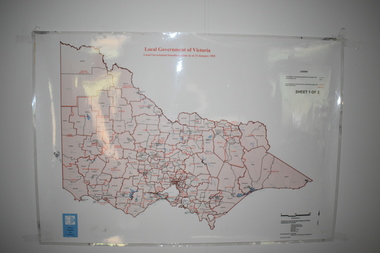
... Victoria. It is Sheet I of 2 and has red and blue pencil markings and black boundary markings. .2 This is a copy of a plan of a survey in black and white markings on paper. .3 This is a plan of the title details of Section 19 Warrnambool. It has black printing on buff-coloured paper. .4 This is a plan of the allotments in part of the Central Business District of Warrnambool. It is printed in black and white. .5 This is a 2006 coloured aerial...Victoria. It is Sheet I of 2 and has red and blue pencil markings and black boundary markings. .2 This is a copy of a plan of a survey in black and white markings on paper. .3 This is a plan of the title details of Section 19 Warrnambool. It has black printing on buff-coloured paper. .4 This is a plan of the allotments in part of the Central Business District of Warrnambool. It is printed in black and white. .5 This is a 2006 coloured aerial ...These ten documents (maps, plans, photographs) mostly come from the Warrnambool City Council and most contain information on sub-divisions and titles of properties in areas around the Central Business District of Warrnambool. The dates range from 1986 to 2006. These maps, plans and photographs are of some interest as they give historical details of subdivisions in Warrnambool and date from the late 20th century. .1 This is a laminated map of the boundaries of Local Governments in Victoria. It is Sheet I of 2 and has red and blue pencil markings and black boundary markings. .2 This is a copy of a plan of a survey in black and white markings on paper. .3 This is a plan of the title details of Section 19 Warrnambool. It has black printing on buff-coloured paper. .4 This is a plan of the allotments in part of the Central Business District of Warrnambool. It is printed in black and white. .5 This is a 2006 coloured aerial photograph of the harbour at Warrnambool – Breakwater etc. .6 This is a 2006 coloured aerial photograph of the Lake Pertobe area in Warrnambool .7 This is a coloured aerial photograph of Warrnambool’s streets over-stamped with road numbers in large blockings. .8 This is a plan showing the title details of Section 11 in Warrnambool. It has black printing on buff-coloured paper. .9.1 This is a plan of sub-divisions in parts of Crown Allotments 38 & 39 in Warrnambool. It has green, pink and yellow markings with black printing. .9.2 This is a plan of the sub-divisions in parts of Allotments 38 & 39 in Warrnambool. It has pink, yellow and blue markings with black printing. It is somewhat faded. warrnambool c.b.d. maps and plans, history of warrnambool -
Villa Alba Museum
Document, Villa Alba Museum Archaeological Test Excavations, 2002
... survey field books and aerial photographs. Secondly, soils surrounding the Villa Alba mansion, which have been found to be contaminated with lead will need to be removed up to a depth of up to 0.6 metres. Removal of deposits from the site may have an adverse impact on any archaeological remains existing below the surface. Contents: Acknowledgements / Abbreviations / List of figures / List of tables / List of plates / Introduction / Historical context / Methodology / Results and interpretations / Discussion / Recommendations / References / Appendix 1 - Plates / Appendix 2 - Content list / Appendix 3 - Copy of Heritage Victoria permit. ...A preliminary report on archaeological test excavations, conducted on 5 & 7 September 2002 by Maddy Atkinson (Ripple Arc). The purpose of the excavations was twofold. Firstly, to conduct subsurface testing at Villa Alba to determine the presence, location and depth below ground of archaeological remains relating to a number of landscape features identified in historical plans, photographs, survey field books and aerial photographs. Secondly, soils surrounding the Villa Alba mansion, which have been found to be contaminated with lead will need to be removed up to a depth of up to 0.6 metres. Removal of deposits from the site may have an adverse impact on any archaeological remains existing below the surface.Contents: Acknowledgements / Abbreviations / List of figures / List of tables / List of plates / Introduction / Historical context / Methodology / Results and interpretations / Discussion / Recommendations / References / Appendix 1 - Plates / Appendix 2 - Content list / Appendix 3 - Copy of Heritage Victoria permit.non-fictionA preliminary report on archaeological test excavations, conducted on 5 & 7 September 2002 by Maddy Atkinson (Ripple Arc). The purpose of the excavations was twofold. Firstly, to conduct subsurface testing at Villa Alba to determine the presence, location and depth below ground of archaeological remains relating to a number of landscape features identified in historical plans, photographs, survey field books and aerial photographs. Secondly, soils surrounding the Villa Alba mansion, which have been found to be contaminated with lead will need to be removed up to a depth of up to 0.6 metres. Removal of deposits from the site may have an adverse impact on any archaeological remains existing below the surface. conservation studies, conservation reports, archaeological reports, villa alba museum -
Villa Alba Museum
Document, Maddy Maitri (Maitri Archaeology), Villa Alba Landscape Reconstruction: Archaeological Test Excavations Phase 2, 2002
... survey field books and aerial photographs. This information would then be used by the landscape architect in the development of a design which approximates the 1880s/1890s landscape of Villa Alba. Contents: Acknowledgements / Abbreviations / List of figures / List of tables / List of plates / Introduction / Historical context / Methodology / Results and interpretations / Discussion / Recommendations / References / Appendix 1 - Plates / Appendix 2 - Content list / Appendix 3 - Copy of Heritage Victoria permit. ...This document documents the results of archaeological excavations conducted within the grounds of Villa Alba in Kew, by Maddy Maitri (Maitri Archaeology) in October 2002. The testing was conducted as part of the design development stage of a proposed landscape reconstruction. The broad aim of subsurface testing at Villa Alba was to determine the presence, location and depth below ground of archaeological remains relating to a number of landscape features identified in historical plans, photographs, survey field books and aerial photographs. This information would then be used by the landscape architect in the development of a design which approximates the 1880s/1890s landscape of Villa Alba.Contents: Acknowledgements / Abbreviations / List of figures / List of tables / List of plates / Introduction / Historical context / Methodology / Results and interpretations / Discussion / Recommendations / References / Appendix 1 - Plates / Appendix 2 - Content list / Appendix 3 - Copy of Heritage Victoria permit. This document documents the results of archaeological excavations conducted within the grounds of Villa Alba in Kew, by Maddy Maitri (Maitri Archaeology) in October 2002. The testing was conducted as part of the design development stage of a proposed landscape reconstruction. The broad aim of subsurface testing at Villa Alba was to determine the presence, location and depth below ground of archaeological remains relating to a number of landscape features identified in historical plans, photographs, survey field books and aerial photographs. This information would then be used by the landscape architect in the development of a design which approximates the 1880s/1890s landscape of Villa Alba.villa alba - archaeology, villa alba - garden reconstruction, 2002
