Showing 54 items matching " concrete dam"
-
 Wodonga & District Historical Society Inc
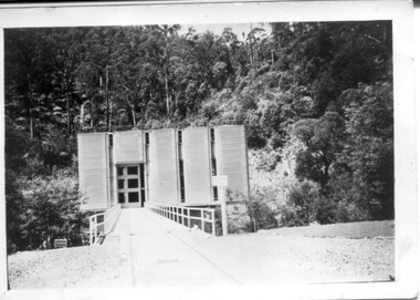
Album - Hume Reservoir Australia Album - View of concrete dam from top of tall tower pillar, August 1927
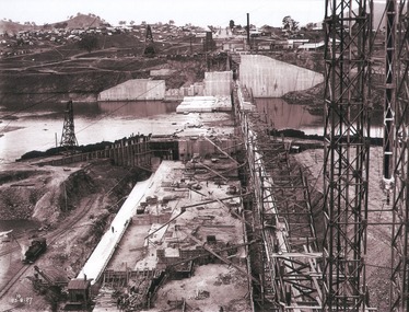
... Hume Reservoir Australia Album - View of concrete dam from top of tall tower pillar, August 1927...Hume Reservoir Australia Album - View of concrete dam from top of tall tower pillar, August 1927...View from Top of Tail Tower Pillar - Concrete Dam. This was taken from the top of the Tower described in the preceding photograph looking towards New South Wales. ...Hume Reservoir Australia Album - View of concrete dam from top of tall tower pillar, August 1927 Album Hume Reservoir Australia Album - View of concrete dam from top of tall tower pillar, August 1927 ...This set of photos is from a leather bound album bearing the inscription "HUME RESERVOIR AUSTRALIA" plus 'The Rt. Hon. L. C. M. S. Amery, P. C., M .P.' all inscribed in gold. It was presented to The Rt. Hon. L. C. M. S. Amery, P. C., M. P, Secretary of State for Dominion Affairs on the occasion of his visit to the Hume Reservoir on 2nd November 1927. This album is of local and national significance as it documents the planning and development of the Hume Reservoir up to 1927. It was the largest water reservoir in the British Empire. The album records the pioneering engineering work that went into its construction.DEPARTMENT OF PUBLIC WORKS, N.S.W. RIVER MURRAY WATERS SCHEME. HUME RESERVOIR. 29. View from Top of Tail Tower Pillar - Concrete Dam. This was taken from the top of the Tower described in the preceding photograph looking towards New South Wales. (WHS 00722) First is the part of the spillway being built inside the Coffer Dam, then over the Coffer Dam the submerged portion of the Spillway and outlet sections for the river diversion, beyond that the situation for the hydro-electric turbo passages bounded by the North Wing Wall. The gap may be seen in wing wall for the passage of the belt conveyor and half of the concrete mixer house behind. This gives a general view of the New South Wales Township. The Quarry is on the side of the hill showing up beyond the Township. New South Wales, August 1927.hume reservoir australia, river murray waters scheme, hume reservoir construction -
 Bendigo Historical Society Inc.
Document - VICTORIA HILL - NOTES ON SIGNS FOR VICTORIA HILL
... ... concrete dam...Sign posts listed are for: Ballerstedt's First open Cut, Quartz Veins (Spurs), Prospecting Shafts 1929, Engine beds for Lansell's big 180 Mine, 20 Head Crushing Battery Stampers, concrete dam, Victoria Quartz Mine, Foundations of steel poppet legs of the Victoria Quartz Mine, Victoria Quartz Dams, Rae's Open Cut, Site where the quartz was roasted, Anticlinal Arch , coloured rock formations, primitive tunnels, Adit, Engine bed for Great Central Victoria, Prospecting Tunnels, Great Central Victoria (Midway). ...Sign posts listed are for: Ballerstedt's First open Cut, Quartz Veins (Spurs), Prospecting Shafts 1929, Engine beds for Lansell's big 180 Mine, 20 Head Crushing Battery Stampers, concrete dam, Victoria Quartz Mine, Foundations of steel poppet legs of the Victoria Quartz Mine, Victoria Quartz Dams, Rae's Open Cut, Site where the quartz was roasted, Anticlinal Arch , coloured rock formations, primitive tunnels, Adit, Engine bed for Great Central Victoria, Prospecting Tunnels, Great Central Victoria (Midway). ...Three page typed copy of notes for signs on Victoria Hill. Mentions items to be seen at Victoria Hill. Sign posts listed are for: Ballerstedt's First open Cut, Quartz Veins (Spurs), Prospecting Shafts 1929, Engine beds for Lansell's big 180 Mine, 20 Head Crushing Battery Stampers, concrete dam, Victoria Quartz Mine, Foundations of steel poppet legs of the Victoria Quartz Mine, Victoria Quartz Dams, Rae's Open Cut, Site where the quartz was roasted, Anticlinal Arch , coloured rock formations, primitive tunnels, Adit, Engine bed for Great Central Victoria, Prospecting Tunnels, Great Central Victoria (Midway). Notes prepared by Albert Richardson.document, victoria hill, notes on signs for victoria hill, gold mines hotel, ballerstedt's first open cut, quartz veins (spurs), prospecting shafts 1929, engine beds for lansell's big 180 mine, 20 head crushing battery stampers, concrete dam, victoria quartz mine, foundations of steel poppet legs of the victoria quartz mine, victoria quartz dams, rae's open cut, site where the quartz was roasted, anticlinal arch , coloured rock formations, primitive tunnels, adit, engine bed for great central victoria, prospecting tunnels, great central victoria (midway), a richardson -
 Bendigo Historical Society Inc.
Document - VICTORIA HILL - THE RICH VICTORIA HILL 150,000 OZ OF GOLD IN SIX YEARS
... ... Concrete Dam...History House 11 Mackenzie Street Bendigo goldfields DOCUMENT Gold victoria hill Victoria Hill The Rich Victoria Hill 150 000 oz of Gold in Six Years Gold Mines Hotel Rotary Club of Bendigo South City Council Bendigo and District Tourist Association Lansell's 180 Victoria Quartz Central Deborah Mine Ballerstedt's First Open Cut Theodore Ballerstedt Ballerstedt's 2nd Open Cut 20 Head Crushing Battery Stampers Concrete Dam Victoria Quartz Mine Rae's Open Cut Quartz Roasting Great Central Victoria (Midway) A Richardson Typed notes titled The Rich Victoria Hill - 150,000 oz of Gold in Six Years. ...Typed notes titled The Rich Victoria Hill - 150,000 oz of Gold in Six Years. Some handwritten notes have been added. Notes give a brief outline of the Victoria Hill. It also mentions the signposts at Victoria Hill.document, gold, victoria hill, victoria hill, the rich victoria hill 150, 000 oz of gold in six years, gold mines hotel, rotary club of bendigo south, city council, bendigo and district tourist association, lansell's 180, victoria quartz, central deborah mine, ballerstedt's first open cut, theodore ballerstedt, ballerstedt's 2nd open cut, 20 head crushing battery stampers, concrete dam, victoria quartz mine, rae's open cut, quartz roasting, great central victoria (midway), a richardson -
 Eltham District Historical Society Inc
Photograph, George W. Bell, Smiths Dam, Eltham, 1961, 1961
... Black and white photograph of concrete dam on Smith property Karingal Drive Eltham 1961...Eltham District Historical Society Inc 728 Main Rd Eltham melbourne karingal drive st helena road d.b smith eltham west drain karingal creek st helena creek dams george w bell collection Black and white photograph of concrete dam on Smith property Karingal Drive Eltham 1961 Smiths Dam, Eltham, 1961 Photograph George W. ...Black and white photograph of concrete dam on Smith property Karingal Drive Eltham 1961karingal drive, st helena road, d.b smith, eltham west drain, karingal creek, st helena creek, dams, george w bell collection -
 Bendigo Historical Society Inc.
Document - VICTORIA HILL - FURTHER SIGNS, VICTORIA HILL
... Signs include Quartz Veins, Prospecting Shaft, 1929, Concrete Dam, Anticlinal Arch New Chum Line, Engine Beds for Gt Central Victoria (Midway Mine), Prospecting Tunnels, Primitive Tunnel. ...Signs include Quartz Veins, Prospecting Shaft, 1929, Concrete Dam, Anticlinal Arch New Chum Line, Engine Beds for Gt Central Victoria (Midway Mine), Prospecting Tunnels, Primitive Tunnel. ...Handwritten carbon copy, and later typed copy, of a list of further signs for Victoria Hill. Signs include Quartz Veins, Prospecting Shaft, 1929, Concrete Dam, Anticlinal Arch New Chum Line, Engine Beds for Gt Central Victoria (Midway Mine), Prospecting Tunnels, Primitive Tunnel. Notes at the end: Given to Geo & Max Ellis on 31/3/1971 and Prospecting tunnels driven from small Open Cut in 1860's. Notes prepared by Albert Richardson.document, memo, victoria hill, victoria hill, further signs victoria hill, new chum line, gt central victoria (midway mine), victoria quartz, davis, geo ellis, max ellis -
 Glenelg Shire Council Cultural Collection
Photograph, n.d
... Closer view of concrete pipes? Soil saving dam....Glenelg Shire Council Cultural Collection History House Cliff Street Portland great-ocean-road Sourced from Casterton Town Hall (former Shire of Glenelg) Back: Black stamp '57' 'Soil Saving Dam looking upstream' 'Gb 4239' - handwritten, pencil Black and white photo. Same section of gully as item number 7238, but looking upstream. Closer view of concrete ...Sourced from Casterton Town Hall (former Shire of Glenelg)Black and white photo. Same section of gully as item number 7238, but looking upstream. Closer view of concrete pipes? Soil saving dam.Back: Black stamp '57' 'Soil Saving Dam looking upstream' 'Gb 4239' - handwritten, pencil -
Tatura Irrigation & Wartime Camps Museum
Photograph, 13/04/1918
... Eildon Weir / Original structure 1918 / Rock and earth fill dam wall / concrete spillway (lower left) / Water middle distance / hills beyond...Eildon Weir / Original structure 1918 / Rock and earth fill dam wall / concrete spillway (lower left) / Water middle distance / hills beyond Photograph ...Taken by photographer for State Rivers and Water Supply Commission.Medium sized black and white photograph. Eildon Weir / Original structure 1918 / Rock and earth fill dam wall / concrete spillway (lower left) / Water middle distance / hills beyondgoulburn weir, victorian state rivers and supply commission -
 Bendigo Historical Society Inc.
Document - RAE'S CRUSHING BATTERY - THE RICH VICTORIA HILL & ITS HISTORICAL ASSOCIATIONS
... Mentioned are:- North Old Chum Mine, Ballerstedt's First Open-cut, Quartz Veins (Spurs), rock formations pitching North, Prospecting shafts 1929, Concrete dam, Engine beds of Lansells Big 180 Mine, Lansells Big 180 Shaft, twenty stampers crushing battery, Lansell's Cleopatra Needle type chimney, Victoria Quartz Mine, Victoria Quartz dams, Rae's Open-cut, Quartz once roasted here to an intense heat, Anticlinal Arch New Chum Line, small primitive tunnels, Prospecting tunnels, Floyd's small 5 head crushing battery, Great Central Victoria (Midway) Shaft, Great Central Victoria engine-bed, Ballerstedt's small 24 yard claim, The Humboldt, Adventure ground, The Advance, Luffsman & Sterry's Claim, A round shaft. ...Mentioned are:- North Old Chum Mine, Ballerstedt's First Open-cut, Quartz Veins (Spurs), rock formations pitching North, Prospecting shafts 1929, Concrete dam, Engine beds of Lansells Big 180 Mine, Lansells Big 180 Shaft, twenty stampers crushing battery, Lansell's Cleopatra Needle type chimney, Victoria Quartz Mine, Victoria Quartz dams, Rae's Open-cut, Quartz once roasted here to an intense heat, Anticlinal Arch New Chum Line, small primitive tunnels, Prospecting tunnels, Floyd's small 5 head crushing battery, Great Central Victoria (Midway) Shaft, Great Central Victoria engine-bed, Ballerstedt's small 24 yard claim, The Humboldt, Adventure ground, The Advance, Luffsman & Sterry's Claim, A round shaft. ...The first five pages are photocopies of photos:- 2 of Rae's Crushing Works; Victoria Quartz on Victoria Hill, Ironbark; Looking North from Old Chum Hill to the Victoria Hill; Victoria Hill - from Rae's Open Cut. Introduction covers location of buildings and mines. Mentioned are:- North Old Chum Mine, Ballerstedt's First Open-cut, Quartz Veins (Spurs), rock formations pitching North, Prospecting shafts 1929, Concrete dam, Engine beds of Lansells Big 180 Mine, Lansells Big 180 Shaft, twenty stampers crushing battery, Lansell's Cleopatra Needle type chimney, Victoria Quartz Mine, Victoria Quartz dams, Rae's Open-cut, Quartz once roasted here to an intense heat, Anticlinal Arch New Chum Line, small primitive tunnels, Prospecting tunnels, Floyd's small 5 head crushing battery, Great Central Victoria (Midway) Shaft, Great Central Victoria engine-bed, Ballerstedt's small 24 yard claim, The Humboldt, Adventure ground, The Advance, Luffsman & Sterry's Claim, A round shaft. Small piece of paper with 'Notes on Victoria Hill complete. Notes prepared by Albert Richardson.document, gold, rae's crushing battery, rae's crushing battery, rae's crushing works, victoria quartz mine, from old chum hill, victoria hill from rae's open cut, ironbark, hercules & energetic, midway, wittscheibe, great central victoria, mr & mrs conroy, central nell gwynne, gold mines hotel, john brown knitwear factory, new chum & victoria, rotary club of bendigo south, north old chum, ballerstedt's first open-cut, lansell's big 180 shaft, cleopatra needle type chimney, a roberts & sons, mr e j dunn, h harkness & sons, eureka extd, new chum railway, pearl, inrush of water at victoria quartz, floyd's small 5 head crushing battery, great central victoria (midway), ballertedt's small 24 yard claim, humboldt, humboldt, great central victoria, victoria hill, bendigo & vicinity 1895 p51, j n macartney 1st edition 1871, bendigo goldfield registry 1871, plan of new chum line, mr rae anderson, annals of bendigo obituary 1904, bendigo advertiser, b m l records mines dept, patterson's goldfields of victoria, dickers mining record 23/11/1861, australian mining standard special edition 1/6/1899 p40, bendigo mines ltd, chinese joss house, fortuna, the victoria goldfield 1851 to 1954, the victoria hill 1854 to 1949 -
 Bendigo Historical Society Inc.
Document - VICTORIA HILL - KEY TO SIGN POSTS ON AREA MAP
... Special Sign Post, No 2 C Rock Formations Pitching North, No 2 B Rich shallow shafts, No 2 A Quartz veins, No 4 A Concrete Dams, No 3 Engine Beds - Lansell's 'Big 180' Mine, No 3 B Lansell's 'Big 180' Shaft, No 4 Twenty Stampers Crushing Battery, No 3 C Foundations - 'Cleopatra Needle' type Chimney for Lansell's 'big 180' Mine, No 5 Victoria Quartz Mine, No 5 A Fou;ndations Victoria Quartz Poppet Legs, No 5 C Foundations Victoria Quartz Winding Plant, No 5 B Victoria Quartz Dams, No 6 Rae's Open - Cut, No 9 Quartz Once Roasted Here, No 12 Anticlinal Arch, No 15 primitive Tunnels, No 14 Beautifully Coloured Rock Formations, No 16 Adit, Graded Bedding, Oblique Fault, Spurry Quartz Veins, No 17 Prospecting Tunnels, No 18 Floyd's Small Crushing Battery, No 19 Gt Central Victoria (Midway) Shaft, No 20 Great Central Victoria (Midway) Engine Bed, No 21 ballerstedt's Small 24 Yard Claim, No 22 Humboldt Shaft, No 23 Wittscheibe's 'Jeweller's Shop', No 24 The 'Adventure' ground, Large Open - Cut, No 26 Luffsman and Sterry's Ground, NO 27 A Round Shaft, Notes prepared by Albert Richardson....Special Sign Post, No 2 C Rock Formations Pitching North, No 2 B Rich shallow shafts, No 2 A Quartz veins, No 4 A Concrete Dams, No 3 Engine Beds - Lansell's 'Big 180' Mine, No 3 B Lansell's 'Big 180' Shaft, No 4 Twenty Stampers Crushing Battery, No 3 C Foundations - 'Cleopatra Needle' type Chimney for Lansell's 'big 180' Mine, No 5 Victoria Quartz Mine, No 5 A Fou;ndations Victoria Quartz Poppet Legs, No 5 C Foundations Victoria Quartz Winding Plant, No 5 B Victoria Quartz Dams, No 6 Rae's Open - Cut, No 9 Quartz Once Roasted Here, No 12 Anticlinal Arch, No 15 primitive Tunnels, No 14 Beautifully Coloured Rock Formations, No 16 Adit, Graded Bedding, Oblique Fault, Spurry Quartz Veins, No 17 Prospecting Tunnels, No 18 Floyd's Small Crushing Battery, No 19 Gt Central Victoria (Midway) Shaft, No 20 Great Central Victoria (Midway) Engine Bed, No 21 ballerstedt's Small 24 Yard Claim, No 22 Humboldt Shaft, No 23 Wittscheibe's 'Jeweller's Shop', No 24 The 'Adventure' ground, Large Open - Cut, No 26 Luffsman and Sterry's Ground, NO 27 A Round Shaft, Notes prepared by Albert Richardson. ...Three page hand written carbon copy of Sign numbers at Victoria Hill. No 1 North Old Chum Shaft, No 2 Ballerstedt's First Open - Cut. Special Sign Post, No 2 C Rock Formations Pitching North, No 2 B Rich shallow shafts, No 2 A Quartz veins, No 4 A Concrete Dams, No 3 Engine Beds - Lansell's 'Big 180' Mine, No 3 B Lansell's 'Big 180' Shaft, No 4 Twenty Stampers Crushing Battery, No 3 C Foundations - 'Cleopatra Needle' type Chimney for Lansell's 'big 180' Mine, No 5 Victoria Quartz Mine, No 5 A Fou;ndations Victoria Quartz Poppet Legs, No 5 C Foundations Victoria Quartz Winding Plant, No 5 B Victoria Quartz Dams, No 6 Rae's Open - Cut, No 9 Quartz Once Roasted Here, No 12 Anticlinal Arch, No 15 primitive Tunnels, No 14 Beautifully Coloured Rock Formations, No 16 Adit, Graded Bedding, Oblique Fault, Spurry Quartz Veins, No 17 Prospecting Tunnels, No 18 Floyd's Small Crushing Battery, No 19 Gt Central Victoria (Midway) Shaft, No 20 Great Central Victoria (Midway) Engine Bed, No 21 ballerstedt's Small 24 Yard Claim, No 22 Humboldt Shaft, No 23 Wittscheibe's 'Jeweller's Shop', No 24 The 'Adventure' ground, Large Open - Cut, No 26 Luffsman and Sterry's Ground, NO 27 A Round Shaft, Notes prepared by Albert Richardson.mine, gold, victoria hill, victoria hill, victoria hill key to sign posts on area map, north old chum shaft, ballerstedt's first open cut, lansell's big 180 shaft, 'cleopatra needle' type chimney, victoria quartz mine, rae's open cut, prospecting tunnels, floyd's small crushing battery, gt central victoria (midway) shaft, ballerstedt's small 245 yard claim, humboldt shaft, wittscheibe's 'jeweller's shop', adventure, luffsman and sterry's ground, david sterry, sterry's 'gold mines' hotel, round shaft -
 Kiewa Valley Historical Society
Photograph of Clover Dam foundations, Clover Dam Foundations, 1949
... dam...foundations...concrete...Stripping of the foundations commenced in 1948 and the first concrete in the dam was poured in May, 1949. With the suspension for the winter months of work on the High Plains, it was possible to increase the number of men, and work then proceeded at a steady pace for the remainder of the year. ...Black and white photograph taken during the construction of Clover Dam. Shows early stages of the concrete foundations, cranes and the railway line which was constructed to bring materials to the site. ...Kiewa Valley Historical Society Mount Beauty Information Centre 31 Bogong High Plains Rd Mt Beauty high-country Stripping of the foundations commenced in 1948 and the first concrete in the dam was poured in May, 1949. With the suspension for the winter months of work on the High Plains, it was possible to increase the number of men, and work then proceeded at a steady pace for the remainder of the year. ...Stripping of the foundations commenced in 1948 and the first concrete in the dam was poured in May, 1949. With the suspension for the winter months of work on the High Plains, it was possible to increase the number of men, and work then proceeded at a steady pace for the remainder of the year. Some interruption was caused by a flood in September, which over topped the rockfill coffer dam. By the end of 1950 17,000 yards of material had been excavated from the foundations and 4,000 cubic yard of concrete placed. Work at Clover Dam was completed in 1953, but two bays were left open for flood emergency. The pondage was filled on the 16th August, 1954. A pictorial record of the placing of concrete foundations of Clover Dam and also shows the methods of construction used at this site in 1949.Black and white photograph taken during the construction of Clover Dam. Shows early stages of the concrete foundations, cranes and the railway line which was constructed to bring materials to the site. Handwritten in blue ink of back of photograph "Clover Dam Foundations"dam, foundations, concrete, construction -
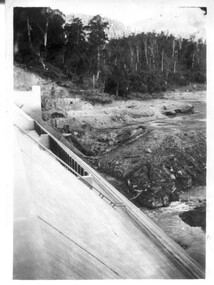
 Wodonga & District Historical Society Inc
Album - Hume Reservoir Australia Album - Section of completed coffer dam, January 1927
... Section of completed coffer dam with river diverted over the concrete foundations of dam that were placed during the first stage of operations. ...Section of completed coffer dam with river diverted over the concrete foundations of dam that were placed during the first stage of operations. ...This set of photos is from a leather bound album bearing the inscription "HUME RESERVOIR AUSTRALIA" plus 'The Rt. Hon. L. C. M. S. Amery, P. C., M .P.' all inscribed in gold. It was presented to The Rt. Hon. L. C. M. S. Amery, P. C., M. P, Secretary of State for Dominion Affairs on the occasion of his visit to the Hume Reservoir on 2nd November 1927. This album is of local and national significance as it documents the planning and development of the Hume Reservoir up to 1927. It was the largest water reservoir in the British Empire. The album records the pioneering engineering work that went into its construction.DEPARTMENT OF PUBLIC WORKS, N.S.W. RIVER MURRAY WATERS SCHEME. HUME RESERVOIR. 20. Section of completed coffer dam with river diverted over the concrete foundations of dam that were placed during the first stage of operations. New South Wales. January 1927. Cofferdams are temporary structures used where construction is being carried out in areas submerged in water. They are most commonly used to facilitate the construction or repair of dams, piers and bridges. To divert the river, a Coffer Dam was built across the old bed above and below the Dam site and tying into the end of the concrete wall built inside the levee bank. This completely surrounded the remainder of the site of the Dam and south wing wall, including an area of 12½ acres. hume reservoir australia, river murray waters scheme, hume reservoir construction -
 Eltham District Historical Society Inc
Photograph - Digital Photograph, Marguerite Marshall, Smith Dam, Karingal Drive, Eltham, 19 September 2006
... Dams'. It was the first time this medal had been awarded outside the United States. The concrete arched dam across the Eltham West Drain was built in 1940 by B.A. ...Dams'. It was the first time this medal had been awarded outside the United States. The concrete arched dam across the Eltham West Drain was built in 1940 by B.A. ...The dam at the entrance to the Nerreman Gateway in Eltham was built according to an internationally acclaimed theory developed by the builder's father. In 1920, Victorian engineer B.A. Smith was awarded the American Society of Civil Engineers J. James R. Cross Gold Medal for his Technical Paper titled 'Arched Dams'. It was the first time this medal had been awarded outside the United States. The concrete arched dam across the Eltham West Drain was built in 1940 by B.A. Smith's son and engineer, D. B. (Bernie) Smith to water the 24 acre (9.75 ha) hobby farm owned by himself and new wife, Isa Smith. Upon completion of the dam a pump-house was constructed beside the creek but before the water could be pumped up the hill they had to dig a trench and lay 500m of 100mm water main to an elevated holding tank. The Smiths made the pump-house their home for several years until they constructed their home at the top of the hill overlooking Eltham and views extending to Kinglake. Following Bernie's death in 1983, Nerreman Park was subdivided between 1993 and 1995. Gordon Ford designed the landscaping and the pump-house was demolished. Covered under Heritage Overlay, Nillumbik Planning Scheme. Published: Nillumbik Now and Then / Marguerite Marshall 2008; photographs Alan King with Marguerite Marshall.; p137 The dam at the entrance to the Nerreman Gateway in Eltham, was built according to an internationally acclaimed theory developed by the builder’s father. In 1920, Victorian engineer B A Smith was awarded the American Society of Civil Engineers J. James R. Croes Gold Medal, for his Technical Paper titled Arched Dams. It was the first time this medal had been awarded outside America. An international example of the application of Smith’s work can be found in the design of the Hoover Dam on the Colorado River, Nevada, USA. Built between 1930 and 1936, it is recognised by the ASCE as one of ‘America’s Seven Modern Civil Engineering Wonders’.1 The concrete arched dam across the Eltham West Drain was built by B A Smith’s son and engineer, D B (Bernie) Smith. Bernie’s dam followed his father’s theory, having a curvature that takes maximum advantage of concrete’s great strength in compression. The water load is carried into the abutments because of this curvature, which permits a wall thickness of only 225 millimetres thick at its crest, despite the dam’s capacity of more than 4.5 megalitres. The Eltham dam was designed to water the 24 acre (9.75 ha) hobby farm belonging to newly married couple Bernie and Isa Smith. Bernie, from Armadale, and Isa, from a farm at Tyntynder near Swan Hill, were attracted to the hilly topography and the creek running through the property. It extended from Ryans Road, Eltham, to Karingal Drive, Montmorency and was adjacent to Meruka Park. The Smiths named it Nerreman Park using the Aboriginal word Nerreman meaning ‘River Bend’ as their creek had a pronounced bend.2 In 1940 the first thing Bernie did was to build a dam, and with Isa’s help, a pump-house, to secure a water supply for their cattle, pigs, chickens, orchard and vegetable gardens. It was also available for the fire-plugs, which they placed all over the property in case of bushfire. The couple built the pump-house beside the creek and installed a Tange three-plunger pump, which had originally supplied the City of Wodonga with water. But before the Smiths could pump water up the hill from the dam they had to dig a trench and lay about 550 yards (500m) of a four-inch (100mm) water main up to an elevated holding tank. The trench was dug with a single furrow plough drawn by an old draught horse. Living in rough conditions did not deter the Smiths, who made the pump-house their home, where they still lived when their first child was born in 1944. They later built their home at the top of their property overlooking Eltham, with magnificent views to Kinglake, the Dandenong Ranges and Melbourne. From 1946 it took them almost 20 years to complete the 36-square house with its 12-foot (3.6m) high ceilings. Material for the concrete roof and walls faced with sandstone, was ripped out of the ground on their property by plough pulled by tandem Clydesdale horses. Isa was a strong woman – two days before their second child was born – she set three huge sandstone boulders in place in the bottom wall of the garage. She also mixed all the cement for the house. A collapsed kitchen wall did not discourage her from rebuilding it in a week, while her husband was away working in the country. She later recalled: ‘We stood back to admire this beautiful wall we’d built and while we were looking at it, it came tumbling down’.3 Following Bernie’s death in 1983, Nerreman Park was subdivided, between 1993 and 1995. Local Gordon Ford designed the landscaping and the pump-house was pulled down. But the dam remains as a reminder of exceptional engineering4 – and of a remarkable couple.This collection of almost 130 photos about places and people within the Shire of Nillumbik, an urban and rural municipality in Melbourne's north, contributes to an understanding of the history of the Shire. Published in 2008 immediately prior to the Black Saturday bushfires of February 7, 2009, it documents sites that were impacted, and in some cases destroyed by the fires. It includes photographs taken especially for the publication, creating a unique time capsule representing the Shire in the early 21st century. It remains the most recent comprehenesive publication devoted to the Shire's history connecting local residents to the past. nillumbik now and then (marshall-king) collection, eltham, karingal drive, smiths dam, bernie smith, gordon ford, isa smith, nerreman gateway, nerreman park estate, dams -
 Wodonga & District Historical Society Inc
Album - Hume Reservoir Australia Album - General View of Works from New South Wales end, Looking Upstream, August 1927
... It extends from the concrete mixer house, which is out of the picture, behind the wing wall, along almost the entire length of the concrete portion of the dam. The concrete is discharged from the belt at any desired point by means of trippers, one of which may be seen over the second trestle. ...It extends from the concrete mixer house, which is out of the picture, behind the wing wall, along almost the entire length of the concrete portion of the dam. The concrete is discharged from the belt at any desired point by means of trippers, one of which may be seen over the second trestle. ...This set of photos is from a leather bound album bearing the inscription "HUME RESERVOIR AUSTRALIA" plus 'The Rt. Hon. L. C. M. S. Amery, P. C., M .P.' all inscribed in gold. It was presented to The Rt. Hon. L. C. M. S. Amery, P. C., M. P, Secretary of State for Dominion Affairs on the occasion of his visit to the Hume Reservoir on 2nd November 1927. This album is of local and national significance as it documents the planning and development of the Hume Reservoir up to 1927. It was the largest water reservoir in the British Empire. The album records the pioneering engineering work that went into its construction.DEPARTMENT OF PUBLIC WORKS, N.S.W. RIVER MURRAY WATERS SCHEME. HUME RESERVOIR. 22. General View of Works from New South Wales end, Looking Upstream. Features: At the left, part of the North Wing Wall, the highest part of which is 26 feet below its ultimate height. Below in the foreground is the portion of the dam where provision is to be made for hydro-electric generation. The tubes, three in number, 13 feet in diameter, will be laid on the level shown and an early start will be made in laying them. The level for the other four regulating outlets, 9 feet in diameter, together with a part of the spillway section of the dam, is underwater at this stage and it may be remarked that at one point, about half way across the channel where the water is now flowing, the concrete foundations are about 80 feet below the level of the water. The broken surface of the water is due to the large “plums” in the concrete. The still water in the right foreground is the stilling pool over the concrete floor of which there is now more than 20 feet of water and by means of which the discharge from the outlet pipes will be quelled. The trestlework on the upstream side of the dam carries the concrete belt conveyor. It extends from the concrete mixer house, which is out of the picture, behind the wing wall, along almost the entire length of the concrete portion of the dam. The concrete is discharged from the belt at any desired point by means of trippers, one of which may be seen over the second trestle. On the other side of the flowing water is the coffer dam. A channel 300 feet wide involving about 140,000 cubic yards of excavation and dug for the temporary diversion of the river as it is flowing now. To the right top of the view beyond the Coffer Dam is the earth embankment being thrown across the major part of the valley by the Victorian Constructing Authority. The Mitta Mitta River flows into the Murray at the far end of the reach of water on the left. August 1927.hume reservoir australia, river murray waters scheme, hume reservoir construction -
 Eltham District Historical Society Inc
Photograph - Digital Photograph, Alan King, Maroondah Aqueduct Siphon Bridge over the Plenty River, 26 January 2008
... In 1920 work began on the present concrete Maroondah Dam one mile (1.6km) from the weir on the Watts River. ...In 1920 work began on the present concrete Maroondah Dam one mile (1.6km) from the weir on the Watts River. ...Opened in 1891, the bridge formed part of the Maroondah Aqueduct carrying water from Watts River near Healesville to the reservoir at Preston where it joined Melbourne's metropolitan water system. Covered under Heritage Overlay, Nillumbik Planning Scheme. Published: Nillumbik Now and Then / Marguerite Marshall 2008; photographs Alan King with Marguerite Marshall.; p99 Built to supply thirsty Melbourne in the late 19th century, the siphon bridge spanning the Plenty River off Leischa Court, Greensborough, was part of an engineering masterpiece. Opened in 1891, the bridge formed part of the Maroondah Aqueduct carrying water from the Watts River near Healesville to the reservoir at Preston where it joined the metropolitan distribution system. A major link in Melbourne’s water supply, it also had a huge impact on communities, which mushroomed along its route. Named after the Aboriginal word for the area around the Maroondah Reservoir, the Maroondah Aqueduct was fully operational until the 1970s. Since the 1980s the land along parts of the aqueduct have been used for walking and bicycle riding, shaded in places by Monterey Pine trees planted to stabilise the surrounding ground. From 1857 the Yan Yean Reservoir supplied Melbourne’s water but the growing city needed additional catchments.1 In 1886 work began on a weir on the Watts River to enable the aqueduct to carry most of the river water 41 miles (66km) to Melbourne. The aqueduct, built by the Board of Works, is the oldest remaining aqueduct near Melbourne and was probably the first built with concrete.2 Although the aqueduct is now only used between the Maroondah and Sugarloaf Reservoirs, it can still be traced across the Shire. It extends from the Maroondah Reservoir through Christmas Hills, Kangaroo Ground, Research, Eltham, St Helena and then previously wound west through Greensborough to Reservoir.3 Built by horse and manpower the aqueduct gravity fed 25 million gallons (113.6ML) of water a day to Melbourne along a gradient of one foot to the mile. It included 25 miles (41km) of open concrete and brick channel, six miles (10km) of tunnels, and nine miles (15km) of 14 inverted siphons of riveted wrought-iron across creeks. Bricks for the aqueduct were made from clay found near the sites and remains of several kilns can still be found between Kangaroo Ground and Christmas Hills. Building the aqueduct transformed local communities. An abattoir was established at Christmas Hills. Grog shanties and labourers’ camps sprang up and local courts dealt with cases of ‘petty pilfering and boisterous behaviour’.4 The Kangaroo Ground school population jumped to 91, crammed into a room with one teacher. Miners who built the tunnels camped just north of Churinga in Greensborough – then called Tunnel Hill Camp – and adjacent to the Evelyn Arms Hotel. The miners’ high spirits were sometimes quenched in horse troughs or by a ‘welt under the ear and kick on the behind’ as the local constable calmed them down rather than lock them up.5 But the growing city of Melbourne needed more water, so the O’Shannassy catchment, east of Warburton, was added to the system in 1914. In 1920 work began on the present concrete Maroondah Dam one mile (1.6km) from the weir on the Watts River. The aqueduct capacity was thus doubled to 50 million gallons (227ML) a day.6 Intense land development threatened to pollute the open water supply, so channel sections were replaced with large pipes. In the late 1960s a large water main was built from the tunnel outlet at Research and extended through St Helena and Greensborough, so this section of the aqueduct was taken out of use. Long sections of the unused open channels in Greensborough and Bundoora were destroyed, but the old channel in Research and Eltham North remained largely intact. In the 1970s, the Sugarloaf Reservoir was constructed, inundating 445 hectares of land in Christmas Hills. Sugarloaf was officially opened in 1980 and serves as a water storage and treatment plant supplying Melbourne. In the early 1980s pipes replaced the section from Sugarloaf Reservoir to the tunnel entrance at Kangaroo Ground. The Research-Kangaroo Ground tunnel operates as part of the pipeline system.This collection of almost 130 photos about places and people within the Shire of Nillumbik, an urban and rural municipality in Melbourne's north, contributes to an understanding of the history of the Shire. Published in 2008 immediately prior to the Black Saturday bushfires of February 7, 2009, it documents sites that were impacted, and in some cases destroyed by the fires. It includes photographs taken especially for the publication, creating a unique time capsule representing the Shire in the early 21st century. It remains the most recent comprehenesive publication devoted to the Shire's history connecting local residents to the past. nillumbik now and then (marshall-king) collection, maroondah aqueduct, pipe bridge, siphon bridge -
 Kiewa Valley Historical Society
Photo - Junction Dam Construction, Circa 1940's
... Junction (Lake Guy) Dam is a 'slab and buttress' type wall. A timber frame is built and then filled with concrete. ...Kiewa Valley Historical Society Mount Beauty Information Centre 31 Bogong High Plains Rd Mt Beauty high-country Junction (Lake Guy) Dam is a 'slab and buttress' type wall. A timber frame is built and then filled with concrete. ...Junction (Lake Guy) Dam is a 'slab and buttress' type wall. A timber frame is built and then filled with concrete. The first batch of concrete was placed in September, 1940. By June, 1941 the buttresses were finished to a height safe from floods and in October of that year a flood of 2,800 cusecs occurred but with only slight damage to the installations. Industrial trouble caused some delays but there was also slow progress on the part of the contractor and the work was taken over by the S.E.C., terminating the contract. The dam was completed in March, 1944. A walkway was made through the dam wall. Lake Guy was named after Mr. L.T. Guy who was the Resident engineer, in charge of construction work and associated activities on the Kiewa Area from 1939 to November 1946Photos of the construction of the Junction Dam detail the harsh conditions faced by construction workers, building dams and villages to accommodate workers in the 1940s to the 1950s. Australia at this period in time, experienced a surge of population (influx of World War II refugees), which was the catalyst for developing and undergoing an enormous hydroelectricity program for the Alpine regions, both in Victoria and New South Wales. This program was initiated to supply electricity to the major southern Australian cities of Adelaide, Melbourne and Sydney. It was thought that these developments would reduce, if not eliminate, the requirement for coal driven power stations. However time has demonstrated that these power stations have not matched the demand required by the industries and the populations of the major urban and cities.Black and white photograph of Junction Dam constructionjunction dam, bogong, secv -
 Kiewa Valley Historical Society
Photo - Junction Dam Diversion Tunnel
... Junction (Lake Guy) Dam is a 'slab and buttress' type wall. A timber frame is built and then filled with concrete. ...Kiewa Valley Historical Society Mount Beauty Information Centre 31 Bogong High Plains Rd Mt Beauty high-country Junction (Lake Guy) Dam is a 'slab and buttress' type wall. A timber frame is built and then filled with concrete. ...Junction (Lake Guy) Dam is a 'slab and buttress' type wall. A timber frame is built and then filled with concrete. The first batch of concrete was placed in September, 1940. By June, 1941 the buttresses were finished to a height safe from floods and in October of that year a flood of 2,800 cusecs occurred but with only slight damage to the installations. Industrial trouble caused some delays but there was also slow progress on the part of the contractor and the work was taken over by the S.E.C., terminating the contract. The dam was completed in March, 1944. A walkway was made through the dam wall. Lake Guy was named after Mr. L.T. Guy who was the Resident engineer, in charge of construction work and associated activities on the Kiewa Area from 1939 to November 1946.Diversion dams are installed to raise the water level of a body of water to be redirected. The redirected water is used for hydro electric power generation. A diversion tunnel is usually bored through solid rock next to the dam site to bypass the dam construction site. The dam is built while the river flows through the diversion tunnel.Photos of the construction of the Junction Dam detail the harsh conditions faced by construction workers, building dams and villages to accommodate workers in the 1940s to the 1950s. Australia at this period in time, experienced a surge of population (influx of World War II refugees), which was the catalyst for developing and undergoing an enormous hydroelectricity program for the Alpine regions, both in Victoria and New South Wales. This program was initiated to supply electricity to the major southern Australian cities of Adelaide, Melbourne and Sydney. It was thought that these developments would reduce, if not eliminate, the requirement for coal driven power stations. However time has demonstrated that these power stations have not matched the demand required by the industries and the populations of the major urban and cities.Black and white photograph of Junction Dam diversion tunnel at Bogong VillageHandwritten on back - Junction Dam Diversional Tunnelbogong, secv, junction dam, lake guy -
 Kiewa Valley Historical Society
Photograph - Junction Dam spilling
... Junction (Lake Guy) Dam is a 'slab and buttress' type wall. A timber frame is built and then filled with concrete. ...Kiewa Valley Historical Society Mount Beauty Information Centre 31 Bogong High Plains Rd Mt Beauty high-country Junction (Lake Guy) Dam is a 'slab and buttress' type wall. A timber frame is built and then filled with concrete. ...Junction (Lake Guy) Dam is a 'slab and buttress' type wall. A timber frame is built and then filled with concrete. The first batch of concrete was placed in September, 1940. By June, 1941 the buttresses were finished to a height safe from floods and in October of that year a flood of 2,800 cusecs occurred but with only slight damage to the installations. Industrial trouble caused some delays but there was also slow progress on the part of the contractor and the work was taken over by the S.E.C., terminating the contract. The dam was completed in March, 1944. A walkway was made through the dam wall. Lake Guy was named after Mr. L.T. Guy who was the Resident engineer, in charge of construction work and associated activities on the Kiewa Area from 1939 to November 1946Photos of the construction of the Junction Dam detail the harsh conditions faced by construction workers, building dams and villages to accommodate workers in the 1940s to the 1950s. Australia at this period in time, experienced a surge of population (influx of World War II refugees), which was the catalyst for developing and undergoing an enormous hydroelectricity program for the Alpine regions, both in Victoria and New South Wales. This program was initiated to supply electricity to the major southern Australian cities of Adelaide, Melbourne and Sydney. It was thought that these developments would reduce, if not eliminate, the requirement for coal driven power stations. However time has demonstrated that these power stations have not matched the demand required by the industries and the populations of the major urban and cities.Black and white photograph of Junction Dam spilling at Bogong VillageHandwritten in pencil - Junction Dam spillingbogong, junction dam, lake guy, secv -
 Kiewa Valley Historical Society
Two black and white photos, Photo downstream view of Junction Dam Wall and photo of Bogong Village and Lake Guy, c1950
... Photo No. 1 - Junction Dam wall was commenced in February, 1940 and completed in March 1944. Type - reinforced concrete slab and buttress. ...Kiewa Valley Historical Society Mount Beauty Information Centre 31 Bogong High Plains Rd Mt Beauty high-country Photo No. 1 - Junction Dam wall was commenced in February, 1940 and completed in March 1944. Type - reinforced concrete slab and buttress. ...Photo No. 1 - Junction Dam wall was commenced in February, 1940 and completed in March 1944. Type - reinforced concrete slab and buttress. Height 25.9m, and crest length 121.9m. Lewis Construction company had the original contract, but was replaced by the State Electricity Commission in 1942. Photo No. 2 - Bogong Village was the first village built to house workers and their families working on the Hydro electric scheme. Construction commenced 1940. The single men's quarters are slightly right of centre on the foreshore. Lake Guy was named after a former resident engineer.Shows the type of terrain where the village is located resulting in the tiered layout that was necessary in order to erect housing.set of 2 black and white photos - Photo No. 1 - downstream view of Junction Dam Wall Photo No. 2 - Lake Guy and Bogong Village. Both are on photographic paperPhoto No. 1 - Upper right hand corner, back of photo, handwritten in ink or biro, Bogong 1950 Photo No. 2 - Left lower corner, front of photo in white, Bogong.bogong village, lake guy, secv -
 Kiewa Valley Historical Society
Photograph of Bogong Dam Wall Construction - 2 identical photos, c1940
... This was completed in February 1940 and excavation for the dam wall commenced in the same month, with the first batch of concrete placed in September. ...This was completed in February 1940 and excavation for the dam wall commenced in the same month, with the first batch of concrete placed in September. ...Excavation of a diversion tunnel was commenced in 1939 to divert water from the East Kiewa River to allow construction of the dam wall. This was completed in February 1940 and excavation for the dam wall commenced in the same month, with the first batch of concrete placed in September. Lewis construction Company had the contract, but the S.E.C. took over construction in March 1942 and the dam was completed in March 1944. Type of construction: reinforced concrete, slab buttress.Importance in the Kiewa area as it shows the formwork and preparation necessary before the pouring of concrete for the first dam in the Kiewa Hydro Electric SchemeBlack and white photos (2 identical) of early construction of Junction Dam wall, viewed from downstream.Back of photo, upper right hand corner: No. 1 - Construction of Bogong Dam Wall (written in pencil) No. 2 - Same as one (written in pencil)construction, dam wall, excavation, bogong, secv -
 Kiewa Valley Historical Society
Black and white photo of Junction Dam wall under construction, c1940
... dam wall. This was completed in February, 1940. Lewis Construction Company had the contract with excavation starting in February and the first batch of concrete placed in September. ...Of historical importance in the Kiewa area as it shows the form work and preparation necessary before the pouring of concrete for the first dam in the hydro electric scheme. ...In December of 1939 the excavation of a diversion tunnel was commenced to divert water from the East Kiewa River to allow construction of the dam wall. This was completed in February, 1940. Lewis Construction Company had the contract with excavation starting in February and the first batch of concrete placed in September. In 1942 the SECV took over the construction and the wall was completed in March, 1944. Type of construction: Reinforced concrete, slab buttress.Of historical importance in the Kiewa area as it shows the form work and preparation necessary before the pouring of concrete for the first dam in the hydro electric scheme. The destruction caused by the 1939 bushfires is also evident in the upper left hand cornerBlack and white photo, early construction of Junction Dam Wall, viewed from downstreamOn back of photo (left hand upper corner) Junction Dam 5-4-81 Dam viewed from downstream. 352 Time to use for correct exp. 40 sec.bogong, junction dam, secv -
 Kiewa Valley Historical Society
Black and white photograph, Early construction of Junction Dam Wall, c1940
... dam wall. This was completed in February 1940. Lewis Construction Co. had the contract with excavation starting in February and the first batch of concrete placed in September. ...Of historical importance in the Kiewa area as it shows the form work and preparation necessary before the pouring of concrete for the first dam in the hydro electric scheme. ...In December of 1939 the excavation of a diversion tunnel was commenced to divert water from the East Kiewa River to allow construction of the dam wall. This was completed in February 1940. Lewis Construction Co. had the contract with excavation starting in February and the first batch of concrete placed in September. In 1942 the S.E.C. took over the construction and the wall was completed in March, 1944. Type of construction: reinforced concrete slab buttress.Of historical importance in the Kiewa area as it shows the form work and preparation necessary before the pouring of concrete for the first dam in the hydro electric scheme. The destruction caused by the 1939 bushfires is also evident in the upper left hand corner.A black and white photograph of the early construction of Junction Dam wall viewed from downstreamOn back of photograph (left hand upper corner) Junction Dam 4-4-81 Dam viewed from downstream 352 Time to use for correct Exp. 40 secjunction dam, bogong, secv -
 Kiewa Valley Historical Society
12 small black and white photgraphs of Junction Dam and surrounding area, Photo No. 1 c1940, all others c 1948
... Stiff leg derricks were erected at appropriate locations at the site of the dam and used for the disposal of excavated material and the placing of concrete. ...Stiff leg derricks were erected at appropriate locations at the site of the dam and used for the disposal of excavated material and the placing of concrete. ...Junction Dam is a reinforced slab and buttress type construction and was commenced in February, 1940 by Lewis Construction Company. Stiff leg derricks were erected at appropriate locations at the site of the dam and used for the disposal of excavated material and the placing of concrete. A rock crushing and screening plant was established at a site a short distance upstream from the dam site and concrete was supplied from a central mixing plant placed close to the upstream toe of the structure. The SEC took over the construction in April 1942 and the dam wall was completed in March, 1944. Bogong township was commenced in early 1940 with the construction of a workmen's camp housing 96 men, (known as Junction camp). Construction of housing for families commenced shortly after. Forty houses, plus office, workshops, stores and laboratory accommodation were completed over the next 5 years,Of historical significance as a pictorial record of Junction Dam, Lake Guy and Bogong Village, as the photos were taken only 4 years after completion and one photo taken on completion of the dam wall but before the lake was filled with water.12 small black and white photographs of Junction Dam, Bogong Village and surrounding area.Photo 1 - On the back upper edge in pen 'Junction Dam'. Then '12' in pencil, circular stamp, printed in centre 'Print by Willson White Albury'. Photo 2 - On the back upper edge in pen 'Junction Dam October 1948'. Stamp as no. 1 photo. Stamp '998L' lower centre. Photo 3 - on the back upper edge in pen 'Junction Dam October 1948'. Circular stamp with 'Kodak Print' . Lower centre back is stamped 'velox' and '998L'. Photo 4 - upper back, in ink - 'Junction Dam Spion Kopje in background. October 1948'. Stamps as photo no. 4. Photo 5 - upper back, in ink - 'Lake Guy (orange filter) October 1948'. Centre back, in pencil '29' and circular stamp with words 'Print by Willson White Albury'. Photo 6 - upper back edge 'Junction, Bogong from Radio Receiving Shack Dec. 1948'. In pencil '14'. Photo 7 - On back of photo 'View of Mountains from Little Arthur Fire Track October 1948'. Two circular stamps with 'Kodak Print', another two stamps - 'Velox' and '998L'. Photo 8 - On back in ink 'Loone's Store Bogong with Spion Kopje in background. October 1948'. Lower down, stamps 'Velox' and '998L'. Part of circular stamp with one word 'Kodak'. Photo 9 - on back in ink 'Junction Camp, Bogong Village & Lake Guy from Little Arthur Fire Track. October 1948'. Stamped across writing '998L'. Lower down stamped 'Velox' and circular stamp with words 'Kodak Print'. Photo 10 - on back in ink 'Junction Camp & Bogong Village Lake Guy in Foreground. October 1948'. Stamps as photo 9. Photo 11 - on back in ink 'Junction Camp & Bogong Village, Lake Guy in Foreground. October 1948'. Lower stamp '998L'. Photo 12 - 'Junction of Rocky & Pretty Rivers with tennis courts in foreground October 1948' . Circular stamp with words, 'Print by Willson White Albury'. Number '29' written pencil.junction dam; bogong village; kiewa hydro electric scheme; lake guy -
 Kiewa Valley Historical Society
5 small black and white photos of Clover Dam and Power Station, c1948
... Clover Dam - stripping of foundation area commenced in January 1948 but the final concrete pour was not until 14th August, 1954....Clover Dam - stripping of foundation area commenced in January 1948 but the final concrete pour was not until 14th August, 1954. ...The construction of Clover Power Station was commenced in October 1942 and the power station building was completed in May, 1943. The first machine was placed in service August, 1944 and the second machine in May, 1945. The water discharges directly into Clover Dam and re-used in West Kiewa Station. Clover Dam - stripping of foundation area commenced in January 1948 but the final concrete pour was not until 14th August, 1954.Pictorial history of the early construction undertaken in the building of the Kiewa Hydro Electric Scheme. Clover power station (No. 3 Development) was the first power station to be built .5 small black and white photographsPhoto No. 1 - handwritten in ink on back ' No. 3 Power Station Clover Flat Nov. 1948 Photo No. 2 - handwritten in ink on back 'No. 3 Power Station Clover Flat Nov. 1948 Photo No. 3- handwritten in ink 'Clover Flat looking towards work area of Clover Dam. Taken near #3 PS. Nov. 1948 Photo No 4 - Handwritten in ink 'Preparation for wall of Clover Dam Dec. 1948 Photo No.5 - handwritten in ink 'Preparation for wall o f Clover Dam Dec. 1948. Photo Nos. 1,2 3, on the back have circular stamp with 'Print by Willson White Albury'. In pencil is the number '78'. Photo Nos. 4, 5, have written on the back in pencil, number '14'. construction, clover power station, clover dam, -
 Kiewa Valley Historical Society
5 Photos - Kiewa Hydro Electric Scheme
... 5 black and white photos including: tunnel construction, concrete lining of tunnel, x 2 Dam construction Junction of Clover, Under ground power station McKay or West Kiewa...Kiewa Hydro Electric Scheme Power Stations SECV 5 black and white photos including: tunnel construction, concrete lining of tunnel, x 2 Dam construction Junction of Clover, Under ground power station McKay or West Kiewa 5 Photos - Kiewa Hydro Electric Scheme ...The Kiewa Hydro Electric Scheme was constructed by the State Electricity of Victoria during the 1950s.The photos give an insight into the construction of the tunnels at the power stations on the KHES.5 black and white photos including: tunnel construction, concrete lining of tunnel, x 2 Dam construction Junction of Clover, Under ground power station McKay or West Kiewakiewa hydro electric scheme, power stations, secv -
 Kiewa Valley Historical Society
Photos- Mt Beauty Fire Brigade Competition and SECV construction
... Dam 6 photos 2. Early Mt Beauty, Fire fighting, Kiewa River, Early Kiewa Scheme Plan, surveying, fire tower 6 photos 3. Lake Guy 2 photos, Clover Power station, Bogong Village, Rocky Vally Flying Fox 2 photos 6 photos altogether 4. Tunnelling 6 photos 5. Bogong, Clover etc 6 photos 6. Bogong Creek Raceline 4 photos 7. Concrete...Dam 6 photos 2. Early Mt Beauty, Fire fighting, Kiewa River, Early Kiewa Scheme Plan, surveying, fire tower 6 photos 3. Lake Guy 2 photos, Clover Power station, Bogong Village, Rocky Vally Flying Fox 2 photos 6 photos altogether 4. Tunnelling 6 photos 5. Bogong, Clover etc 6 photos 6. Bogong Creek Raceline 4 photos 7. Concrete ...The State Electricity Commission of Victoria constructed the Kiewa Hydro Electric Scheme (KHES) which included the construction of the towns of Mt Beauty and Bogong from the late 1940s to 1961. The Mt Beauty Fire Brigade was formed to protect the towns and the surrounding areas including the area of the KHES.The KHES changed the Kiewa Valley from a rural community to a construction community. The Mt Beauty fire brigade competed with neighbouring fire brigades to practice their skills and to meet other fire fighters.Small black and white photos of Kiewa Hydro Electric Scheme, including Mt Beauty Fire Brigade competing against other local brigades in the 1950s. Photos include: 1. Junction Dam 6 photos 2. Early Mt Beauty, Fire fighting, Kiewa River, Early Kiewa Scheme Plan, surveying, fire tower 6 photos 3. Lake Guy 2 photos, Clover Power station, Bogong Village, Rocky Vally Flying Fox 2 photos 6 photos altogether 4. Tunnelling 6 photos 5. Bogong, Clover etc 6 photos 6. Bogong Creek Raceline 4 photos 7. Concrete Plant 3 photos 8. High Plains 6 photos 9. Mt Beauty Fire Bridgade 1 & 2 . 8 photos altogether 10. Engineer Michael Walter 1 & 2. 4 photos altogetherNOTE: KVHS has photos for media on USB but won't load onto VIC Collectionskhes, mt beauty fire brigade, engineer michael walter -
 Kiewa Valley Historical Society
Photos - x6 Raceline repairs on the High Plains
... Dam. Part of the Kiewa Hydro Electric Scheme on the Bogong High Plains. Kiewa Hydro Electric Scheme Raceline Water Power Bogong High Plains Alec McCullough Collection 6 black and white photos:- 2 with concrete framework, 2 concrete completed and 2 High Plaines race line. ...As part of the Kiewa Hydro Scheme the race lines were created to catch the water and direct it into the Rocky Valley Storage Dam.Part of the Kiewa Hydro Electric Scheme on the Bogong High Plains.6 black and white photos:- 2 with concrete framework, 2 concrete completed and 2 High Plaines race line.Alec McCullough Collectionkiewa hydro electric scheme, raceline, water power, bogong high plains -
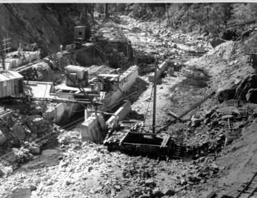
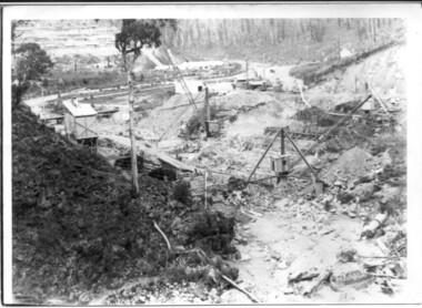
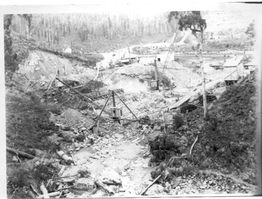
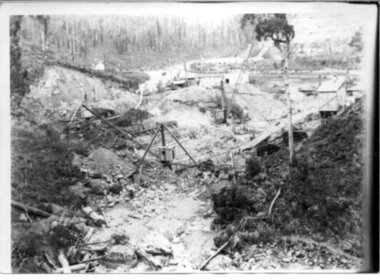
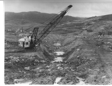 Kiewa Valley Historical Society
Photograph Rocky Valley Dam Excavations, Rocky Valley Dam Wall Excavation, c1947-48
... At the dam site the river was diverted through a temporary pipeline. Work proceeded in the summer months with the placing of concrete in the foundations and earth and rock fill for the construction of the wall. ...At the dam site the river was diverted through a temporary pipeline. Work proceeded in the summer months with the placing of concrete in the foundations and earth and rock fill for the construction of the wall. ...Work commenced at Rocky Valley Dam site in early 1947 and proceeded until May. Resumed work in October after the winter and a camp for the accommodation of workmen was commenced at this time. Work continued in 1948 with the establishment of work facilities, including the erection of two large excavators. At the dam site the river was diverted through a temporary pipeline. Work proceeded in the summer months with the placing of concrete in the foundations and earth and rock fill for the construction of the wall. Rocky Valley and associated spillway and outlet works were completed in March, 1959. A very good representation of the type of machinery available in the 1940's used for excavation of the dam and the construction of the dam wall.Black and white photograph of Rocky Valley Dam wall under construction. There are at least three cranes plus workmen in the photo. This is taken from the Heathey's Spur side of the dam wall looking back toward Sun Valley.Hand written on back of photograph "Rocky Valley Dam Wall Excavation" in blue ink.rocky valley, dam, wall, machinery -
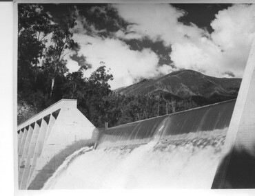 Kiewa Valley Historical Society
Photograph of Lake Guy Dam, Spillway, Lake Guy Dam, c1945
... This is a 'slab and buttress' dam. It is framed with timber and concrete then poured into the structure. ...This is a 'slab and buttress' dam. It is framed with timber and concrete then poured into the structure. ...In December 1939 the excavation of the diversion tunnel at the site of Junction (Lake Guy) Dam was commenced and finished in February, 1940.This allowed the stream to be diverted to facilitate the dam wall construction. This is a 'slab and buttress' dam. It is framed with timber and concrete then poured into the structure. A contract was let to Lewis Construction Co. for the construction of the dam, and the first batch of concrete was placed in September, 1940. Industrial trouble caused some delays but there was also slow progress on the part of the contractor and the work was taken over by the S.E.C., terminating the contract. The dam was completed in March, 1944. The lake is named after Mr. L.T. Guy who was the Resident Engineer, in charge of construction work and associated activities on the Kiewa area, from 1939 until November 1946. An historical pictorial record taken for the State Electricity Commission of Junction Dam (Lake Guy) on spill. Mt. Arthur is in the background and there is still evidence of the destruction of trees from the 1939 bushfires. Black and white photograph of Lake Guy Dam . The dam is spilling and Mt. Arthur is in the background. Hand written on back of photograph in blue ink " Lake Guy Dam".dam, lake, water, mr. l.t.guy -
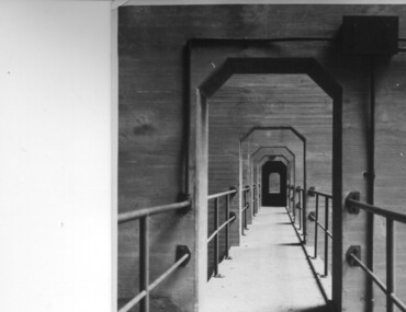 Kiewa Valley Historical Society
Photograph of Lake Guy Dam, Walkway, Inside Lake Guy Dam, c 1945
... Lake Guy Dam is a 'slab and buttress' type wall. A timber frame is built and then filled with concrete. ...Kiewa Valley Historical Society Mount Beauty Information Centre 31 Bogong High Plains Rd Mt Beauty high-country Lake Guy Dam is a 'slab and buttress' type wall. A timber frame is built and then filled with concrete. ...Lake Guy Dam is a 'slab and buttress' type wall. A timber frame is built and then filled with concrete. The first batch of concrete was placed in September, 1940. By June, 1941 the buttresses were finished to a height safe from floods and in October of that year a flood of 2,800 cusecs occurred but with only slight damage to the installations. Industrial trouble caused some delays but there was also slow progress on the part of the contractor and the work was taken over by the S.E.C., terminating the contract. The dam was completed in March, 1944. A walkway was made through the dam wall. Lake Guy was named after Mr. L.T. Guy who was the Resident engineer, in charge of construction work and associated activities on the Kiewa Area from 1939 to November 1946.Shows the walkway placed as part of the Lake Guy (Junction) Dam wall. A very good pictorial reference for the future.Black and white photograph of the walkway through Lake Guy (Junction) Dam wall.Handwritten in blue ink on back of photograph "Inside Lake Guy Dam". slab, buttress, dam, mr. l.t. guy -
 Kiewa Valley Historical Society
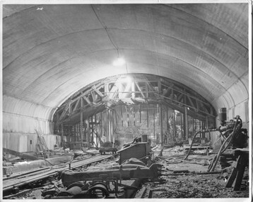
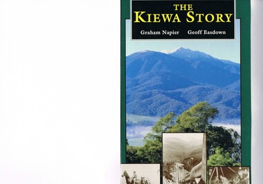
Book - Non Fiction History, The Kiewa Story, circa 1993
... dam containing lake Guy. The inside front cover is a black and white photograph which details the construction of the West Kiewa tailrace tunnel during April 1951. The inside back cover is a black and white photograph of the concrete...dam containing lake Guy. The inside front cover is a black and white photograph which details the construction of the West Kiewa tailrace tunnel during April 1951. The inside back cover is a black and white photograph of the concrete ...This book provides in chronological order the development of the Kiewa Hydro-electricity scheme from the first concept (1911) to final construction work (1961). It covers the first attempt to utilise the power of the Victorian Alps water system. It started from a private syndicate and developed to the current State Electricity Commission of Victoria. The incentive for the Hydro scheme was to make money and not as an alternative to the carbon producing coal fired power plants. These coal fired power plants were increasing in numbers to service an ever increasing demand made by population expansion, especially in cities and large rural settlements. This demand spiraled up after World War II when there was a tremendous spike in immigration numbers due to refugees and displaced persons in Europe. The ability to utilise the untapped water provided by the winter snow fields, for a higher yield in electricity, was a powerful incentive to overcome the physical hardships in this remote Alpine region. Future power requirements may initiate the re-installation of the other two power stations(Pretty Valley and Big Hill) covered in original Scheme. This publication not only covers the development of the Kiewa Valley region with respect to population (within a socio-economical framework) but also the subtle but yet strong physical changes of a relatively pristine alpine region. The demands that an ever growing regional population places on the environment is clearly documented in print and black and white photographs. The working and living conditions of those who constructed and gave life to this hydro scheme is well documented in this book. It may be viewed as spartan now but was relevantly good at that moment in time, especially for those workers fleeing a devastated European environment. The successful planning and consideration to minimising any intrusion upon the natural alpine forests and high plains can viewed as an example (compared to the Tasmanian Hydro schemes) of how future hydro schemes (an inevitable requirement) will proceed. Most rural towns (in the early 1900s) were built by unencumbered rural based citizens, with the exception of Mount Beauty and Falls Creek. These two settlements were brought into life by a State (Victorian) Authority for a specific function and program. They were a gated community, that is, only open to construction workers involved with the hydro scheme. All facilities within these communities were provided by the State Electricity Commission of Victoria. The impact on the social, financial and individual independency of the community, by the transition from the S.E.C .environment to one of local government (Shire of Bright), had in some cases a severe impact.This hard covered book has a green cover with pictures on the front and back covers. The front cover has a coloured picture of a snow covered Mount Bogong taken from the opposite mountain range. The valley between both ranges has a whisk of mist over it. At the bottom of this picture are three black and white photographs covering the construction of the Kiewa Hydro - Electricity Scheme. On the back cover is a photograph, (black and white) detailing the Bogong village and Junction dam containing lake Guy. The inside front cover is a black and white photograph which details the construction of the West Kiewa tailrace tunnel during April 1951. The inside back cover is a black and white photograph of the concrete pour at the Clover Dam circa 1952. All photographs and sketches are in black and white. The pages are approximately 160 g/m2 and those which have photographs are on gloss paper.Book spine: "The Kiewa Story Graham Napier Geoff Easdown" alongside this is a white framed circle with white spokes radiating out and underneath in white lettering SECkiewa valley, hydro scheme, victorian alpine region, electricity generators, graham napier, geoff easdown